

Re: Double Pressure Tank System Or Screw-Feeder
Dear Mr Kaufman,
Am I right that the italic typed text is describing an existing installation and the normal typed text is the to be designed installation?
What do you mean by “from camera”?
Which installation do you want to compare with a double tank system versus a screw feeder?
Is the tankvolume given as total volume or as cement content?
Required are tankvolume and cement volume, in order to calculate the pressurizing time and the unloading time.
The answer to your main question of which installation is more energy efficient is easy to answer.
A double tanksystem serves, just as the screwfeeder, as a feeder system.
The double tanksystem uses almost no energy/ (any pressurizing energy is later on used for pneumatic conveying)
A screwfeeder uses a considerable amount of energy, forcing the cement plug as a seal through the screw feeder barrel. More energy than needed for a tank system.
This is the case when the pneumatic conveying system for both feeders is the same.
When the pneumatic system is designed for each particular technology, the difference in energy consumption per ton changes, but will be in favor of the double tank system.
To calculate your installations, I need the additional information.
best regards
Teus ■
Teus
Re: Double Pressure Tank System Or Screw-Feeder
 Originally Posted by Kaufman
==========================================================
My dear friends Teus Tuinenberg or Mr. Jack Hilbert can surely solve this directly.
but it is your assignment to do this!
You have done most of the work already with the known factors of the system in use.
the twin tanks system allows for continued batching and dilute phase conveying.
Any elbow is a restriction and requires more energy to move the material, any long distance requires more energy. any elbow becomes place where sedimentation/build up can occur.
A solid auger is linear in design and has either a hollow auger or a solid flighting
For long distances you will need several augers with transition hoppers and for simplicities sake an incline auger instead of a vertical auger for the transition to avoid plugging.
Either way (ENERGY) is used with numerous electric motors to power the auger drives or the blower system. The six basic laws of gasses are used you should already understand that.
lzaharis ■
Re: Double Pressure Tank System Or Screw-Feeder
Dear Mr Kaufman,
I calculated your existing cement conveying system with a length of 1000 m.
The results were:
-Pipeline capacity 69.5 tons/hr at 2.5 bar and a pipeline energy consumption of 3.33 kWh/ton
-System capacity 57 tons/hr at 2.5 bar and a system energy consumption of 3.67 kWh/ton
Then I calculated the same pipeline for a screwfeeder, whereby the conveying pressure is reduced to 1.8 bar, which is the maximum pressure a screwfeeder can handle.
Resulting in:
-Pipeline capacity 56.6 tons/hr at 1.8 bar and a pipeline energy consumption of 3.22 kWh/ton
-System capacity 56.6 tons/hr at 1.8 bar and a system energy consumption of 3.92 kWh/ton
-The energy consumption of the screwfeeder is taken as 0.7 kWh/ton at 1.8 bar from an existing installation I once built. A better design of the screwfeeder with a lower energy demand makes the 2 systems more equal.
Manufacturer’s input is here important.
The pipeline energy consumption at 1.8 bar is less than the pipeline energy consumption at 2.5 bar (better pneumatic conveying efficiency)
When applying a screwfeeder, the pressurizing energy and purging energy in a vessel system is avoided and in a comparison used for the screwfeeder.
The long pipeline with a 2 vessel system has an extra issue to attend to.
The rest pressure in an empty vessel is about 0.8 bar that has to be vented from the kettle before a refill can take place. At that moment there is no airflow in the pipeline until the next vessel is released. Therefore, it is necessary that the pipeline is properly purged, to prevent sediment and possible blockage.
The application of a booster, taking care of continuous purging, is a solution.
When applying a screwfeeder, the constant purging is inherent to the system.
A screwfeeder system is simpler and easier to maintain.
Comparing the 2 systems properly, requires the design of two optimal systems.
If you need more information or the output of the calculations, let me know.
Have a nice day
Teus ■
Teus
Re: Double Pressure Tank System Or Screw-Feeder
Originally Posted by Teus TuinenburgDear Teus
The italic typed text is describing existing double pressure tank system
and normal typed text is describing existing pipeline
[QUOTE=What do you mean by “from camera”?[/QUOTE] from chamber
[QUOTE=Which installation do you want to compare with a double tank system versus a screw feeder?[/QUOTE]On existing pipeline:
Pipeline stainless steel with 7 90° bend total horizontal flow 800m; vertical flow 30m pipeline diameter 219mm
[QUOTE=Is the tankvolume given as total volume or as cement content?
Required are tankvolume and cement volume, in order to calculate the pressurizing time and the unloading time.[/QUOTE]
The tankvolume is given as total volume. I don't have information about cement volume, but i guess if productivity of cement mill is 40 tn/h = 0.6667 tn/min so cement volume will be around 0.4733
[QUOTE=The answer to your main question of which installation is more energy efficient is easy to answer.
A double tanksystem serves, just as the screwfeeder, as a feeder system.
The double tanksystem uses almost no energy/ (any pressurizing energy is later on used for pneumatic conveying)
A screwfeeder uses a considerable amount of energy, forcing the cement plug as a seal through the screw feeder barrel. More energy than needed for a tank system.
This is the case when the pneumatic conveying system for both feeders is the same.
When the pneumatic system is designed for each particular technology, the difference in energy consumption per ton changes, but will be in favor of the double tank system.
To calculate your installations, I need the additional information.
best regards
Teus[/QUOTE]
Please explain more clearly, as I realize double tank system use about 4 bar 58m3/min if compressor provide 250m3/min at 1600 kwt/h, than 250m3/min will consume 26.67kwt/min and double tank system is using 6,19 kwt/min
same productivity FK pump 63 tn/h consume 41m3/min at 430m material transportation. So 4,36 kwt/min will be air cost and + 2,2 kwt/min FK pump motor consumption = 6.56 kwt/min + as i know FK pump have more costly maintenance because of cement is abrasive material.
Dear Teus am I right ? Or I just missed something ? I am a civil engineer so a am not good enough in mechanical stuff
p.s. just wondering why FK pumps are so popular ? ■
Re: Double Pressure Tank System Or Screw-Feeder
Originally Posted by Teus TuinenburgAs I know existing system working good when pressure is above 3.5 bar when pressure is 3.0bar then material flow is a bit problematic. What will be your opinion about it ? Or it can be caused of that existing double pressure pumps are old and have a lot of wearing maybe they have a pressure lose ? Did u make calculation for 800m length or it's for 1000m ?
[QUOTE=Then I calculated the same pipeline for a screwfeeder, whereby the conveying pressure is reduced to 1.8 bar, which is the maximum pressure a screwfeeder can handle.
Resulting in:
-Pipeline capacity 56.6 tons/hr at 1.8 bar and a pipeline energy consumption of 3.22 kWh/ton
-System capacity 56.6 tons/hr at 1.8 bar and a system energy consumption of 3.92 kWh/ton
-The energy consumption of the screwfeeder is taken as 0.7 kWh/ton at 1.8 bar from an existing installation I once built. A better design of the screwfeeder with a lower energy demand makes the 2 systems more equal.
Manufacturer’s input is here important.
The pipeline energy consumption at 1.8 bar is less than the pipeline energy consumption at 2.5 bar (better pneumatic conveying efficiency)
When applying a screwfeeder, the pressurizing energy and purging energy in a vessel system is avoided and in a comparison used for the screwfeeder.
The long pipeline with a 2 vessel system has an extra issue to attend to.
The rest pressure in an empty vessel is about 0.8 bar that has to be vented from the kettle before a refill can take place. At that moment there is no airflow in the pipeline until the next vessel is released. Therefore, it is necessary that the pipeline is properly purged, to prevent sediment and possible blockage.
The application of a booster, taking care of continuous purging, is a solution.
When applying a screwfeeder, the constant purging is inherent to the system.
A screwfeeder system is simpler and easier to maintain.
Comparing the 2 systems properly, requires the design of two optimal systems.
If you need more information or the output of the calculations, let me know.
Have a nice day
Teus[/QUOTE]
Can I have output of the calculations plz ? Want to take a look, think will have more questions after that.
I am much obliged for your prompt reply and assistance.
Your faithfully,
Mike ■
Re: Double Pressure Tank System Or Screw-Feeder
Dear Mr Kaufman,
I will calculate the existing 8” pipeline of 800m + 30m.
Your energy calculations are based on a 100% full load of 4bar for the double tank system.
This is in reality not the case as the pressure rises from 0 to opening pressure of the kettle and decreases when purging the pipeline after the kettle is emptied.
Furthermore, I doubt whether the existing system is really reaching 4 bar. (Please check)
A double tank system also requires maintenance, especially on the valves.
And valve failures always occur at inconvenient moments.
A double tank system requires quite a complicated control.
On long pipelines, the kettles need to be bigger, in order to minimize the time lost in changing kettles. To reach a certain overall capacity, the installation needs to be designed for a higher pipeline capacity.
A screwfeeder is simple and reliable for a longer service period (250.000 tons or more).
Maintenance stops can be scheduled and replacing a screwfeeder is easy. Replacing the wearing parts of a screwfeeder is also not a big deal.
Where a double tank system is discontinuous, a screwfeeder is continuous.
When you state 2.2 kWh/t for the FK pump at 63 t/hr, means a motor of 138 kW.
Which type of FK pump is this? I once used FK pumps of 110 kW for 150 tons/hr, which is 0.7 kwh/ton.
Please check the dimension "kwt/min".
Just saw your las reply.
A pneumatic conveying system should work better at lower conveying rates (lower pressures).
I assume that you are taking air from a main system (7 bar) by using sonic chokes or flow regulators. Maybe this equipment is delivering less air at lower pressures. please check.
All for now
Teus ■
Teus
Re: Double Pressure Tank System Or Screw-Feeder
Originally Posted by Teus TuinenburgHere is table of some FK pumps
model--------T-39------40--------41----------42--------54-1----------54
tn/h------------36---------63-------------63--------------110-----------40…70---------70…110
length---------430-------230------------430-------------230----------200…450------200…450
vertical--------30---------30-------------30---------------30------------35
pipeline mm---175------175-------------250-------------250----------175-250-------200-300
screw diameter--190---220-------------230-------------230-----------200-------------250
Air m3/h-------25---------22-------------41---------------38-------------45---------------48
pressure MPa--0.3-------0,2------------0,3--------------0,2------------0.3--------------0.2
motor KWt------75--------55------------132-------------110-----------55-75----------90- 132
A double tank system also requires maintenance, especially on the valves. As i know it's very-very cheap only need to change some ruber and metal rings, only throat is a problem.
Plz can u list Pros an Cons of both systems ? as i read in W. Duda, Cement Data Book FK pumps have 30% more electricity consumption. Unfortunately culdn't find any comparison tables or articles of them. ■
Re: Double Pressure Tank System Or Screw-Feeder
Dear Mr Kaufman,
Attached are the promised calculations.
Reconstructing your table is not easy.
Maybe, you can separate the columns with slashes.
The table gives also conveying lengths, diameters and air volumes.
However, these data are not relevant for the capacity of the screwfeeder.
A screwfeeder injects a certain amount of cement into the pipeline against a certain pressure.
How the pipeline is conveying that amount of cement at the same pressure is not known by the screwfeeder.
A 30% higher power consumption for a screwfeeder pneumatic conveying installation, without giving any secondary references, does not mean anything.
The longer the pipeline is, the less this % will be.
have a nice day
Teus
Attachments
cement pneumatic conveying pipeline 800m_1000m (PDF)
■
Teus
Re: Double Pressure Tank System Or Screw-Feeder
Dear Mr Kaufman,
The table is now clear.
I put the table in a spreadsheet and calculated the “kWh/ton” and “m/sec” values for the respective models.
(see attachment)
The “kWh/ton” for the 2 bar installations are ranging from 1.07 kWh/ton to 2.1 kWh/ton
The “kWh/ton” for the 3 bar installations are ranging from 0.87 kWh/ton to 1.29 kWh/ton
The terminal air velocities are ranging from 12.9 m/sec to 31.8 m/sec.
The product is not mentioned but let us assumes it is cement.
My first comment would be that the conveying pressure should not exceed approx. 1.8 bar.
At higher pressures, there is a chance of stalling the screw and excessive wear.
The velocity range cannot be explained as logical.
The figures are at least a bit confusing.
After you have studied the calculations and commented them, we proceed in this interesting case.
Are you in contact with Fuller?
best regards
Teus
Attachments
■
Teus
Re: Double Pressure Tank System Or Screw-Feeder
Dear Teus Tuinenburg
World of thanks for your assistance !
I carefuly read your data calculations and now have some questions. If u have time I hope u will provide me with answers.
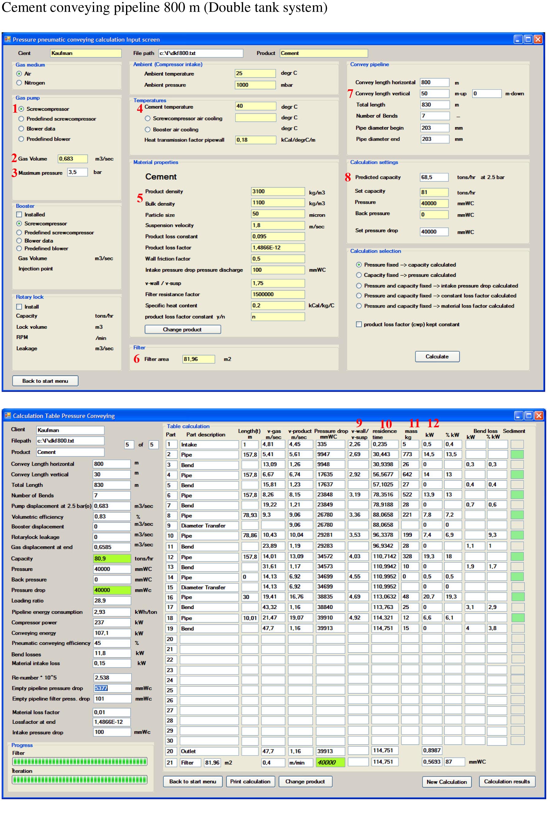
1) why is screwcompresor selected?
2) why 0.683 m3/sec ?
3) why 3,5 bar if we calculating for 4 bar
4) as i know it's up's till 150 C
5) portland cement bulk density is 1440 kg m3 as i know
6) what about filter Area do u need actual data for beter calculation ? Or what kind of data do u need ?
7) why 50 m ? As i described there is 30m
8) predicted capacity why we looking it at 2,5 bar ?
Olso need explanation with 9) 10) 11) 12) can't understan clearly
13) Actually pipe diameter is 219 mm
14) can't understand what does it mean
15) not clear
16) why we took 5 m3 ?
17) why 237 kwt
18) is this right 466 C degree temperature ?
Thank you in advance
Best regards
Mike
Attachments
cement pneumatic conveying pipeline 800m-3 (JPG)
copy of cement pneumatic conveying pipeline 800m-4 (JPG)
■
Re: Double Pressure Tank System Or Screw-Feeder
Dear Mr Kaufman,
1)In most installations, a screwcompressor with internal compression is used above 1 bar. Therefore, my program uses this type of compressor as a default. The only influence on the pneumatic conveying calculation is the consumed power and the outlet temperature. Another type of compressor, incorporated in the program is a blower and a turbine. Other types can manually be corrected.
2)I used 41 m3/min in one of your threads. In the calculations, this choice leads to a working system and is therefore Ok for the time being.
3)The used compressor is for maximum 3.5 bar, but the calculation is not influenced by that figure.
4)If the cement temperature is up to 150 degrC, I can calculate that. Using a double kettle system with rubber-seated valves will be a problem then.
5)You refer to the bulk density in settled condition. In a tank it is in fluidized condition, hence the bulk density is lower.
6)If you have the actual filter data, those values should be used as input. The influence, if properly selected should be minimal.
7)My mistake, I will change it. The influence on the total calculation will be there, but I do not expect a drastic change in the conclusions.
8)That is referring to the chosen compressor. At other pressures, the internal leakage of the compressor is accounted for in the calculation. Internal leakage as a function of the pressure has an influence on the capacity/pressure curve.
9)This value reflects the ratio between the wall velocity of the conveying air in relation to the local suspension velocity. The wall velocity must be higher than the local suspension velocity in order to maintain the particle in suspension. If this ratio becomes lower than a preset value, sedimentation is detected and accounted for in the calculations.
10) This figure represents the time that a particle is travelling in the pipeline from the beginning to the end.
11) This figure reflects the amount of cement in kg that is present in the respective part of the pipeline.
12) The pipe diameter for the calculation must be chosen as the inner diameter. You refer to the outer diameter of 219 mm
13) This figure represents the power used in each respective pipeline section
14)This is a factor representing the unload efficiency of a kettle. If the kettle releases not enough cement into a pipeline, then the designed pressure cannot be reached. In this case no problem.
15) This is also a figure used for the same issue as under 13). Also, no problem for this calculation.
16)The volume in the tank must be less than the total volume of the tank. I guessed 5 m3.
17)The program calculates the 237 kW because of the airflow and the pressure for a screwcompressor with internal compression. In this case, a 2 stage screwcompressor should be calculated or if a sonic choke is used a constant mass flow of air should be calculated.
18)As the screwcompressor is designed for 3.5 bar, the outlet temperature at 4 bar is calculated too high. The influence on the calculation is existing, but is not big, because the mixture temperature is close to the cement temperature and along the pipeline the cooling effect against the environment is accounted for.
Hopefully, the set up and the possibilities of the program becomes a bit more clear now.
If would like to have other calculations executed, it is now only a matter of manipulating the input.
Best regards
Teus
Visit also:
Pneumatic conveying, Performance and Calculations:
https://news.bulk-online.com/?p=65
Dense phase- or dilute phase pneumatic conveying:
https://news.bulk-online.com/?p=238
Pneumatic conveying, turbo- or positive displacement air mover:
https://news.bulk-online.com/?p=309
Energy consumption per ton of a pneumatic conveying system:
https://news.bulk-online.com/?p=331
Pneumatic conveying, an unexpected relationship.
https://news.bulk-online.com/?p=445 ■
Teus
Re: Double Pressure Tank System Or Screw-Feeder
Dear Teus Tuinenburg
First of all, I would like to thank you for your answers. I am very grateful to you for the rendered help.?
On two points I still have questions 11) what is time phase ? and also I am not clear with Total Energy consumption (is it sum of pipeline energy + compressor + conveying+ bend losses+) ?
These two days I’m collecting the information. Here new details were found out.
1)Pipeline from double tank system --> go up 3m -->(bend 90 )-->flat 150m-->(bend 90 )-->flat 168 --> (bend 90 ) --> 22m -->(bend 90 )-->go up 27m --> (bend 90 ) --> 10m --> (bend 90 ) --> 20m --> (bend 90 ) --> discharge
total length 400m
2)There is 2 pipeline. One from each vessel.
3)Gas pump: centrifugal compressor 250m3/min at 1640kwt/h pressure 4 bar (it used for several system)
4)Cement temperature 90-110 C
6)Filter area none
7)Convey length horizontal 370m vertical 30m
8)Pipeline diameter out 219mm inner 200mm
9)Mill productivity 40t/h
Existing Double Pressure Tank System:
Productivity of an unloading of cement from camera, t/h 61.5
Length of transport pipeline, m 1000
Also vertical, m, not longer than 50
air-quantity flow, m3/mun 58
Diameter of transport pipeline (internal diameter), mm 200
Overall dimension, mm: -
Capacity, m3:
of 1 vessel 6.3
of 2 vessels 12.6
Type of uploading upper/top
Can we compare this system with TA 41A model FK pump ?
Also i will find another Fuller pump specifications which works on 1,8 bar.
Best regards
Mike ■
Re: Double Pressure Tank System Or Screw-Feeder
Dear Mike,
11) The amount of cement in a respective part of the pipeline in kg:
If you take a picture of the pipeline (time period = 0), then you will see that there is at that moment x kg cement underway.
Total energy consumption is the totally consumed energy during a conveying cycle divided by the conveyed tons per cycle in kWh/ton for the calculated system.
Consumed energy is, the time weighed, compressor energy + (booster energy) + (feeder energy)
The 273 kW is the consumed power of the compressor.
For your 400 m system, I have the following question:
“3)Gas pump: centrifugal compressor 250m3/min at 1640kwt/h pressure 4 bar (it used for several system)”
How much air is used for the 400 m pneumatic conveying system? ( I need that figure for a the right calculation).
In addition, I would like to know how the amount of conveying air is taken from the compressed air system (Which technology is used. (Flow regulator, sonic choke?)
The centrifugal compressor is probably a turbine, but that is not really important here, because just a part of the air capacity is used through an auxiliary device.
The comparison double tank versus screwfeeder is already done (Cement pneumatic conveying pipeline 800m 1000m.pdf)
The screwfeeder is working independently from the pneumatic conveying system as long as the created conveying pressure can be handled by the screwfeeder.
The TA-41A screwfeeder will work up to 3 bar conveying pressure on any size of pipeline (6”-8”- 10” – 12”etc)
It is better to consult Fuller (Bethlehem USA) for the application of a certain type.
I cannot find any type data on their internet site, which is a pity.
cheers
Teus ■
Teus
Re: Double Pressure Tank System Or Screw-Feeder
Originally Posted by Teus TuinenburgDear Teus
First of all, I beg u pardon for so late answer. I was out of country.
now about questions
1) For pump is used around 60 m3/min
2) Not clear yet about this, as I found there are used valves so can control pressure directly from compressor. Also air temperature at compressor outlet is around 100C
3) Compressor is a turbine
4) Still waiting answers from FK-pump manufacturers
5)I need for 400m and with actual digits ( existing compressor, TA 41A model FK pump, existing Double Pressure Tank System etc. )
Can u calculate systems for 400 ? do you need any additional information for calculation ?
Best regards
Mike ■
Re: Double Pressure Tank System Or Screw-Feeder
Dear Mike,
1)An air volume of 60 m3/min means 1 m3/sec. In combination with an 8” pipeline, the resulting air velocities are between 10 m/sec to 35 m/sec, which is for cement unnecessarily and far too high.
2)You do NOT need a pressure regulator but a flow regulator. To have a constant flow of air from the flow regulator, a pressure regulator before the flow regulator makes the airflow independent from the pressure fluctuations in the main air supply.
3)OK.
4)Keep trying
5)See attachment
Double tank system: System capacity 92 tons/hr at 2.5 bar – 2.37 kWh/ton
Screw feeder system: System capacity 92 tons/hr at 1.8 bar – 3.29 kWh/ton
Screw feeder system: System capacity 82 tons/hr at 1.8 bar – 3.47 kWh/ton
Velocities far too high for cement.
Best regards
Teus
Attachments
cement pneumatic conveying pipeline400m kaufman (PDF)
■
Teus
Re: Double Pressure Tank System Or Screw-Feeder
Dear Teus
Thank you for your brilliant Help
But I am little confusing with this new digits, pipe line capacity and system capacity are enormous compared with 800m calculation digits. Can be 60m3/min a mistake ? I took it from Double tank system manual. Also for FK-Pump 40m3/min
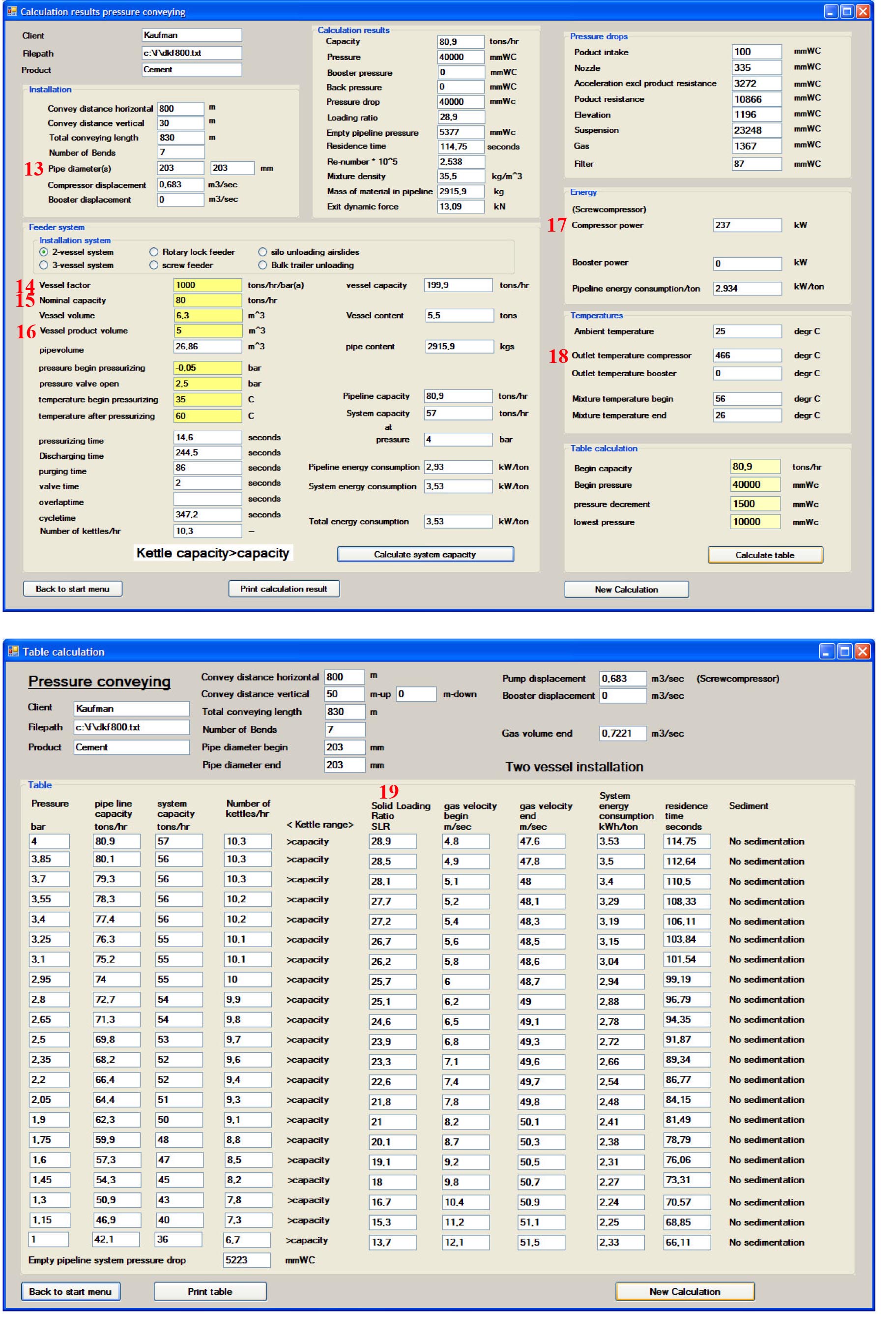
In double tank pressure conveying screen pressure table started from 2.5 bar and it works at 4 bar, so please could you provide me up to 4bar calculation, also some screen missed, there are 5 instead of 8.
Is compressor power usage 239 kw with double tank system right ?
Is it possible to provide me with capacity --> pressure calculation ? 
Best regards
Mike ■
Re: Double Pressure Tank System Or Screw-Feeder
Dear Mike
A 400 m long pipeline can convey a much higher rate of cement than a 800 m pipeline
see:
Pneumatic conveying, an unexpected relationship.
href="https://news.bulk-online.com/?p=445" target="blank">https://news.bulk-online.com/?p=445
Attached the 4 bar calculation with 60 m3/min.
The pressure/capacity gradient becomes very small at the higher pressures, indicating that the risk of plugging is increasing.
A small rise in feeding and the pressure exceeds the available pressure (safety valve opens) and the conveying halts
Whether the 60 m3/min is a mistake, I do not know. I just calculate based on your information.
I cannot judge from here, whether the information is right or reflecting the actual situation.
The “missing” pages do not give necessary extra information.
The program calculates 239 kW and if the programming is correct, it should be OK.
have a nice day
teus
Attachments
cement pneumatic conveying pipeline400m kaufman4ba (PDF)
■
Teus
Re: Double Pressure Tank System Or Screw-Feeder
Dear Teus
I have some question
1) pressure/capacity gradient which one in the tables ?
2) regarding the compressor 1640kw 250m3 if we use 4 double tank system and they consume 60m3 than total 60*4=240m3 therefore one double tank system will consume around 400kw
3) here is some double tank system models in the attached file maybe you will find it interesting for you
4) Is it possible to provide me with capacity --> pressure calculation ? (program another option)
Best regards
Mike ■
Re: Double Pressure Tank System Or Screw-Feeder
Dear Teus
I have some question
1) pressure/capacity gradient which one in the tables ?
2) regarding the compressor 1640kw 250m3 if we use 4 double tank system and they consume 60m3 than total 60*4=240m3 therefore one double tank system will consume around 400kw
3) here is some double tank system models in the attached file maybe you will find it interesting for you
4) Is it possible to provide me with capacity --> pressure calculation ? (program another option)
Best regards
Mike
Attachments
■
Re: Double Pressure Tank System Or Screw-Feeder
Dear Mike,
1)Pressure/capacity gradient is defined as the tangent of the capacity=function(pressure) curve.
At 4 bar it is calculated as (139.5-138.6)/(4-3.95) =18
At 2.5 bar = 23
At 1.5 bar = 35
At 1 bar = 57
At 4 bar conveying pressure, there is less capacity increase required for the same resulting pressure increase, which increases the chance of choking.
2)If your main supply compressor is operating at 7 bar, which pressure is reduced to 4 bar, you are correct. In the mean time you have destroyed approx 400 – 250 = 150 kW in throttling. A more energy efficient system needs to be designed, using dedicated compressors. In addition, the 60 m3/min airflow is not optimal.
3)The attached file, which you refer to, is not included.
4)My program is not available on the market. Mr Agarwal of this forum shares his software (excel sheet) with forum members.
I am interested in your double tank models and will have a look at them for you.
take care
Teus ■
Teus
Re: Double Pressure Tank System Or Screw-Feeder
Originally Posted by Teus TuinenburgDear Teus
1) Please see the attached file above your post. There are 2 of my identical posts second one with attachment
2) I don't need your program I am not mechanical engineer and this work is only part of my training work so because I asked you about another calculation. With known capacity 40tn/h --> what will be best more energy efficient pressure for system ? Please provide help if u can
Thanks a lot in advance and kind regards
Mike ■
Re: Double Pressure Tank System Or Screw-Feeder
Dear Mike,
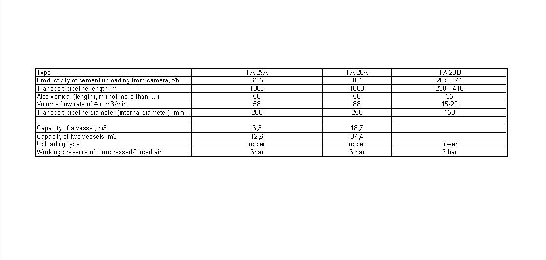
Calculation results of your systems:
TA-29A 1000m:
system capacity 60 tons/hr at 4 bar
TA-28A 1000m:
system capacity 109 tons/hr at 4 bar
TA-23B 230m:
system capacity 40 tons/hr at 2.5 bar
Maximum pressure 2.5 bar because of sedimentation at higher pressures
TA-29B 410m:
system capacity 47 tons/hr at 4 bar
Regarding the 40 t/hr installation:
Please indicate:
- conveying length horizontal
- conveying length vertical
- number of bends
- double tank system?
- screwfeeder ?
best regards
Teus ■
Teus
Re: Double Pressure Tank System Or Screw-Feeder
Originally Posted by Teus TuinenburgDear Teus
I didn't need calculation with different types of Double tanks this was information only for you
Regarding the 40 t/hr installation:
we are talking about same system 400m you have already done calculation (known pressure unknown capacity ). Now for the same system if we use TA-29A or TA-41A what will be lowest working pressure and what will be most energy efficient pressure, this is a question.
and one more question:
As I understand for
TA-29A 1000m:
system capacity 60 tons/hr at 4 bar
and if we use it on 400m system capacity 107 tons/hr at 4 bar
How system capacity increase ?
Thank you for your help, sorry for disturbing you
Mike ■
Re: Double Pressure Tank System Or Screw-Feeder
Dear Mike,
Double tank system 40 tons/hr:
Horizontal length 430 m
Vertical 35 m
Stepped pipediameter 154mm / 203mm
Tank volume 6.3 m3
Material volume 5m3
Screwcompressor: Aerzen VM21R at 20737 rpm (0.394 m3/sec)
System capacity:
48 tons/hr at 2.5 bar – 1.82 kWh/ton
40 tons/hr at 1.5 bar – 1.58 kWh/ton
40 tons/hr on a 1000m long pipeline corresponds with 107 tons/hr on a 400m long pipeline.
have a nice day
Teus ■
Teus
Re: Double Pressure Tank System Or Screw-Feeder
Originally Posted by Teus TuinenburgDear Teus
In old system we have Horizontal length 370m and Vertical 30m instead of as you had calculated (Horizontal length 430 m Vertical 35 m) also pipe diameter 200m.
Can i have calculations outputs for (unknown pressure known capacity ) ?
I already have calculation for (known pressure unknown capacity ) with your help, now want to compare they, with calculation (unknown pressure known capacity ).
best regards
Mike ■
Re: Double Pressure Tank System Or Screw-Feeder
Dear Mike,
The calculations you asked for are attached.
You did not mention the air volume of the installed compressor.
Therefore, I assumed 0.512 m3/sec.
A system capacity of 40 tons/hr generates a “steady” conveying pressure of 0.7 bar.
In practice, the pressure fluctuates in time from 0 to the opening pressure of the tank.
In addition, during purging the pipeline, the pressure drops gradually until the set closing pressure of the tank.
success
Teus
Attachments
cement pneumatic conveying pipeline430m kaufman (PDF)
■
Teus
Re: Double Pressure Tank System Or Screw-Feeder
Good Day
While the input of Teus is very comprehensive, I must let you know that his comments about conveying line pressure of 1.8 bar for the screw pump are misleading to a slight degree as he is limiting his analysis to just one screw pump supplier ( he refers to Fuller)
There are other screw pump manufacturers such as Claudius Peters and IBAU and even FLS ( Fuller) themselves, have an older pump design as well, which can pump against higher line pressures then the 1.8 bar limit for the more recent design "M" type pumps.
Regardless of the pump design - the end result will be the same -- the dual pressure tank will be more energy efficient but the "complete" evaluation can swing either way depending on what specifically you include such as maintenance costs, installation costs, spare parts, man-hours, reliability factors, etc etc
Regards ■
Re: Double Pressure Tank System Or Screw-Feeder
Hello Jack,
Thank you for the addition to my replies.
According to the websites of Claudius Peters and Ibau, they feed up to resp. 3 bar and 2.5 bar.
The required power for the screwpumps is not given for each of the suppliers nor can any claim of low energy consumption be found.
As the power demand is almost proportional to the conveying pressure, a 3 bar feeder system uses twice as much as a 1.5 bar feedersystem.
Of course, this choice influences the pneumatic conveying design a great deal.
For a good project comparison of both systems, it is absolutely necessary to design both systems in various configurations.
Then the evaluation can take place with all the items you mentioned included.
Thanks again
Have a nice day
Teus ■
Teus
Re: Double Pressure Tank System Or Screw-Feeder
Good morning dear Teus
I would like to ask you few question
1)Specific erosion = (Ratio of velocity) involution 2.65 Is thats mean if we will increase conveying speed tnan we need to buy pipe more often ?
2)( Pipe Erosion cost = Specific erosion x pipeline maintenance cost) is it correct ?
3)Do you know were can I read information about Pros and Cons of FK-Pump an also Double tank System ?
Also I would like to ask you about calculations 400m that you have done for me, I need all 8 pages instead of 5 that you had posted in PDF "Cement pneumatic conveying pipeline400m Kaufman.pdf"
Thanks again
Have a nice day
Mike ■
Re: Double Pressure Tank System Or Screw-Feeder
Dear Mike,
1)I am not sure what you mean by “Specific erosion = (Ratio of velocity) involution 2.65”. Increasing the conveying speed will cause more wear, not really on the pipes as well in the bends. However, why increase the velocity, as this will cost also more energy per conveyed ton?
2)I do not know the meaning of that relationship.
3)The reply of Jack covers the whole issue. Energy demand is clearly a pro for the double tank system. All the other parameters depend on the specific installation.
A double tank system is discontinuous and more sensible to choking and a screwfeeder system is 100% continuous.
If you asked for a quotation of both alternative systems, the differences become clear.
An experienced consultant can do the job for you.
4)All 4 screenshots of the installation you asked for are attached.
Take care
Teus
Attachments
cement pneumatic conveying pipeline400m kaufmancom (PDF)
■
Teus
Re: Double Pressure Tank System Or Screw-Feeder
Hello Teus,
How are you doing?
I have one more question for you.
Vertical length:370m
Horizontal length:30m
diameter of pipeline: 200mm
number of bend : 7*90°
material portland cement
3,5 th per 1 cycle and it consumes 232m3 of air per 1 cycle (only transporting, without filling)
cycle time is 4 minute
the pressure in vessel during the cycle is 1,6 bar (pressure gauge shows)
compressor produce 4 bar
the volume of blow vessel: 6,2m^3
air temperature 90c
Pick-up velocity ?
Terminal velocity ?
Material to air ratio ?
4bar compressed air 1m3 weight ?
Dilute or Dense Phase ?
66m3 air per 1 tn is it a lot ?
many thanks again for your very kind cooperation
Cheers!
Mike ■
Re: Double Pressure Tank System Or Screw-Feeder
Dear Mike,
I assume 370m HORIZONTAL
and
30m VERTICAL
Correct?
Stay tuned
Teus ■
Teus
Re: Double Pressure Tank System Or Screw-Feeder
Dear Mike,
Attached the calculation results.
At 1.6 bar(g):
Pick-up air velocity = 13.62 m/sec
Terminal air velocity = 33.62 m/sec
Material to air ratio = 19.1
Air mass of 1 m3 at 4 bar(g) at 90 degrC = 1.293 * 5 * 1 * 273/(273+90) = 4.86 kg
Considering the high velocities for cement, it is most certainly dilute phase conveying.
The compressor displacement = 232/4*60= 3480 m3/h3
The pipeline capacity = 81.4 tons/hr at 1.6 bar(g)
Resulting in 3480/81.4 = 42.75 m3/ton
I suppose it is a little bit high, because of the high air velocities.
Keep in mind that the conveying length is 400 m, limiting the maximum SLR.
Increasing the conveying pressure (by increasing the SLR) to 2.5 bar(g) will increase the system capacity from 72 tons/hr at 1.6 bar(g) to 86 tons/hr.
The energy consumption increases from 2.17 kWh/ton at 1.6 bar(g) to 2.45 kWh/ton at 2.5 bar(g)
At your service
Teus
Attachments
pninstportlandcement400m (PDF)
■
Teus
Re: Double Pressure Tank System Or Screw-Feeder
Dear Teus,
Thanks for your fast reply.
Still have some questions.
(SLR)Material to air ratio = 19.1 transporting material weight / air weight is it right ? so it will 3500kg/232*4,86kg or I have miss something ?
Thanks again
Have a nice day
Mike ■
Re: Double Pressure Tank System Or Screw-Feeder
Dear Mike,
The 232 m3 is atmospheric air displacement (NOT at 4 bar(g)) in 4 minutes.
Therefore, the air mass flow = 232 * 1.293 * 1 * 273/(273+25) = 274.8 kg/4min.
(assuming an intake air temperature of 25 degrC.)
As you calculate the SLR = (3500 kg/4min)/(274.8 m3/4min) = 12.7
3500 kg/4min = 3.5*60/4 = 52.5 tons/hr.
In my calculation, the SLR is calculated as the ratio between the pipeline capacity (excluding pressurizing, purging and filling) and the calculated air mass flow.
In my program, the internal leakage of an (assumed) screwcompressor with internal compression is accounted for at different pressures.
If you have an Aerzen compressor, I can calculate the air flow automatically.
In the screenshots, you can trace the following figures:
1.0038 * 1.293 * 1 *273/(273+26) * 3600 = 4250 kg/hr
SLR = 81400/4250 = 19.1
Accurate definitions of the used figures are essential.
regards
Teus ■
Teus
Re: Double Pressure Tank System Or Screw-Feeder
Dear Mike,
I executed the calculations of the pneumatic conveying installation of 400m for portland cement, in order to verify the conveying regime, dense phase or dilute phase.
The results are presented in the attachment.
My initial guess was far from the reality.
The system is dense phase and the installation working point is in the diagram located just left of the lowest pressure drop, which is the separation between dense- and dilute phase conveying.
It seems that velocity is not such a good indication whether a system is dilute- or dense phase.
The longer length of a conveying installation shifts the difference between dense- and dilute phase conveying towards higher velocities.
Again something learned.
Have a nice day
Teus
Attachments
zenzdiagram400mportlandcement (PDF)
■
Teus
Re: Double Pressure Tank System Or Screw-Feeder
Dear Teus,
Thanks a lot for your help.
Is it possible to calculate 5m3 cement discharge time from the vessel ?
Also interesting if u have information how much is 30m vertical = xxx m horizontal and 90 degree bend = xxx m horizontal ? As I have gathered information 90 degree bend = 8 m horizontal pipe, is it correct ?
Best Regards,
Mike ■
Re: Double Pressure Tank System Or Screw-Feeder
Dear Mike,
In my program, vertical pipelines are calculated as vertical pipelines and horizontal pipelines are calculated as horizontal pipelines.
Consequently, there is no need to convert vertical pipelines into equivalent pipelines.
Moreover, this way of approximations is inaccurate, as they depend on loading ratio.
In bends, only the velocity loss is calculated. The related pressure drop is calculated as subsequent acceleration.
The discharge time for 5 m3 cement is calculated as:
5/6.2 * 242.9 = 195.9 sec. (see calculation pdf)
47 seconds less.
Have a nice day
Teus ■
Teus
Re: Double Pressure Tank System Or Screw-Feeder
Dear Teus,
Can u provide me with the formula to calculate how much m3 air can go through 100mm diameter pipe per minute ?
Cheers!
Mike ■
Re: Double Pressure Tank System Or Screw-Feeder
Dear Mike,
Air volume through a pipe is given by:
Volume at p1 and T1 = velocity * pi/4*D^2
and
Volume at standard conditions p2=1 bar(abs) (Atmospheric) and T2=0 degrC:
Volume in nm3/dt = Volume at p1 and T1 * p1/p2 * T2/T1
or
Volume in nm3/dt = velocity * pi/4*D^2 * p1/1* 273/(273+temp)
Recalculated for every location in a pipeline.
Have a nice day
Teus ■
Teus

Double Pressure Tank System or Screw-Feeder
Double Pressure Tank System or Screw-Feeder (FK-pump)
Hello
For my training work I have to calculate what is better Double Pressure Tank System or Screw-Feeder (FK-pump). Which one is less energy consumption for existing pipe line with Double Pressure Tank System and optimize the pneumatic conveying of cement with air (main target less kwt per tn) .
Some info:
Cement transporting amount 40-45tn/h; 3200cm2/gm blaine
Existing Double Pressure Tank System:
Productivity of an unloading of cement from camera, t/h61.5
Length of transport pipeline, m1000
Also vertical, m, not longer than 50
air-quantity flow, m3/mun 58
Diameter of transport pipeline (internal diameter), mm200
Overall dimension, mm: -
Length 3770
Width 3350
Height 4340
Capacity, m3:
of 1 vessel 6.3
of 2 vessels 12.6
Control system remote
Type of uploading upper/top
Pipeline stainless steel with 7 90° bend total horizontal flow 800m; vertical flow 30m pipeline diameter 219mm
Compressor 250m3/min 7 bar but using bypass on 4 bar (also other users of air are in the system).
Thanks in advance ■