7.2 Design Principle 2 – Ensure Sufficient Cross-Sectional Area
Always ensure that there is sufficient belt cross-sectional area to allow for the free flow of material through different sections of the chute. The formula given in section 5.2.1 must be valid at all sections through the chute.
7.3 Design Principle 3 – Control Stream Of Particles
It is critical to retain control of the material flow through the chute in order to ensure efficient transfer. The following figures and formulae give the design principles employed with both a material stream falling under gravity as well as that where material exits the chute with significant velocity. The case illustrated in Fig. 16 shows slow moving particles exiting the discharge chute and falling through a free-fall vertical portion of the chute onto the curved 'spoon' chute.
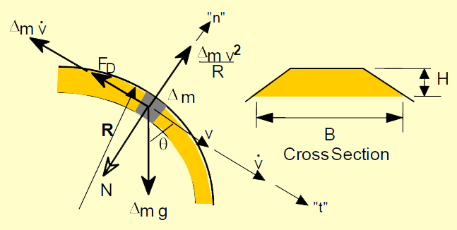
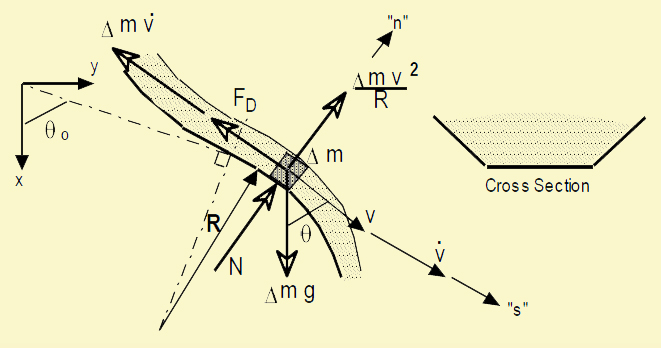
The flow into the curved bottom section of the chute may be illustrated by the free body diagram in Fig. 17.
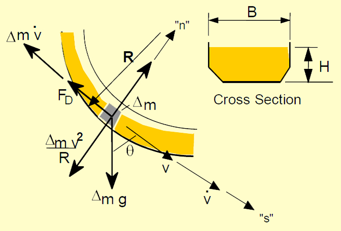
For a chute of rectangular cross-section we find
where: V0 = initial velocity at entry to stream H0 = initial stream thickness Analysing the dynamic equilibrium conditions of Fig. 16 leads to the following differential equation:
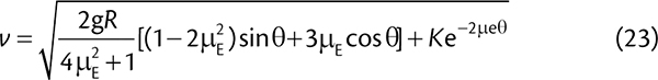
On conditon that the curved section of the chute is of constant radius R and assuming that μE remains constant at an average value for whole of the stream, it may be shown that the solution of the above equation leads to Eq. 23 for the velocity at any location
 |
For v = v0 at θ = θ0
 |
Special case: when θ0 = 0 and v =v0, then
Equation 23 then becomes
 |
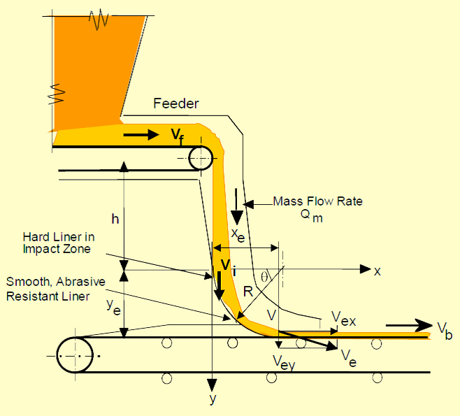
In the generalised case of a belt conveyor transfer point the material leaves the discharge pulley with some inertia in the horizontal direction and hence the material stream has to be channelled into a cohesive stream and controlled through the vertical section and onto the spoon chute. This is illustrated in Fig. 18.
Hence the material flow in the upper hood portion is represented by the free body diagram in Fig. 19.
The formulae developed for the spoon section may be developed for the hood section as
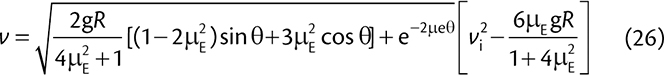
For a constant radius and assuming μE is constant at an average value for the stream, the solution for the velocity equation (17) is
 |
For v = v0 at θ = θ0 then
 |
The above principles may also be applied to the case of a convex curve in the chute as indicated below.
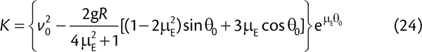
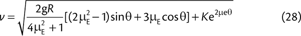
This is applicable for sin θ ≥ v2/Rg. It is noted that Fig. 19 also applies in this case with the vertical axis now representing the maximum value of the velocity for chute contact. For a constant radius and assuming μE is constant at an average value for the stream, the solution for the velocity equation (28) is
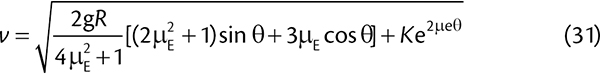 |
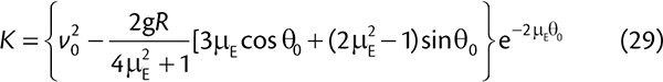
For v = v0 at θ = θ0 then
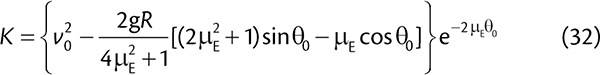 |