3.1 Heavy Duty Catenary Idler
A 5-roll catenary idler string was trialled in the hope that, given its flexibility perpendicular to belt travel, the allowable dynamic travel would remove some of the impact force. Other ‘dynamic’ features of this idler were the rubber isolation mounts and rubber lagging of the idlers. The idler string had no improvement in component life, nor was there any noticeable improvement to belt life. Even though an improvement opportunity may have existed in the way of customising the catenary idler using bigger/more bearings and thicker connecting links (the main failure areas), this would not have improved belt life.

Disadvantages of the catenary idler are the lack of restraint for the idler string to move forward as the belt travels over it. This may provide a worsening of belt tracking, a increase in belt and idler wear and the change in belt profile may cause the belt to come into contact with hard skirts as shown by Conveyor Design Consultants of W.A. [5].
The client also trialled lower durometer rubbers for the lagging, without much success as it tore apart. Whilst the reasoning behind use of low durometer rubber is sound for reducing impact, the reduction of hardness, likely achieved by a reduction in rubber fillers, will sacrifice tensile strength and abrasion resistances from an optimum range as shown by Matador Rubber s.r.o [6]. This may have contributed to its failure in this application.
3.2 Impact Saddle
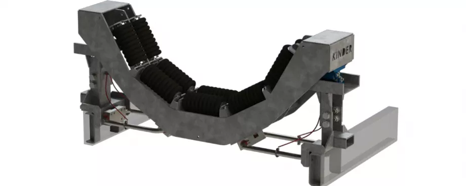
The impact saddle (Fig. 19) was trialled in the hope that some of the impact forces could be reduced by taking advantage of the rubber isolation below the UHMWPE saddle segments (Fig. 20), another form of a dynamic feature.
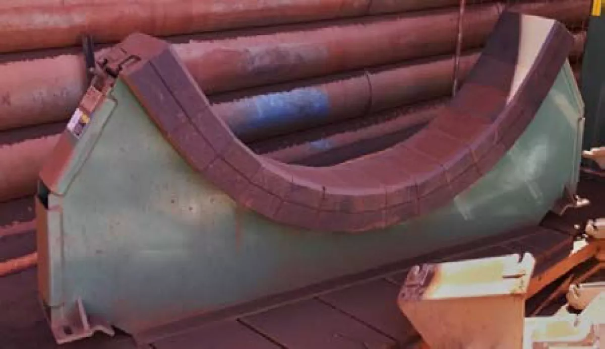
Fig. 19: Impact Saddle.
|
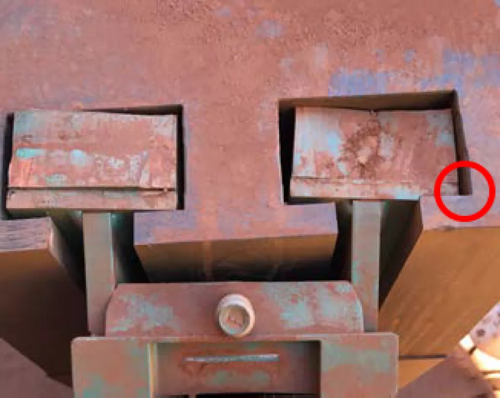
Fig. 20: Impact Saddle rubber cushioning system; a sharp radius in this inner corner (marked by a red circle in the picture) may be contributing to UHMWPE saddle failure.
|
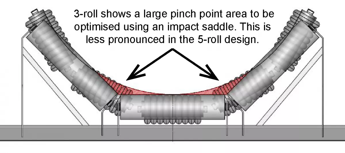
Another advantage of the impact saddle in this configuration is the constant radius of the cradle, reducing the likelihood of pinch point damage of the belt at the idler junctions. Comparing the saddle with a 3-roll trough design, there is much more to be gained in achieving a constant radius (Fig. 21). This issue is less pronounced on this system, due to replacing a 5-roll trough design and therefore had little effect on belt life.
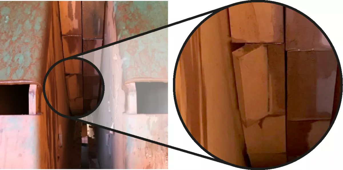
The steel frame was much less susceptible to failure, likely due in part to its completely filled in plate upright design. The UHMWPE saddle segments however suffered from rebound failure, whereby the retaining section would break away (Fig. 22). A reason may be, due to rubber resilience and stiffness of the frame, when the rubber rebounds after impact, the energy in the opposing direction is forcing the segment upwards and overstressing the segment retaining section, especially given its stress concentration due to a sharp internal radius (Fig. 20).