3.3 Custom Stiffened Impact Idler
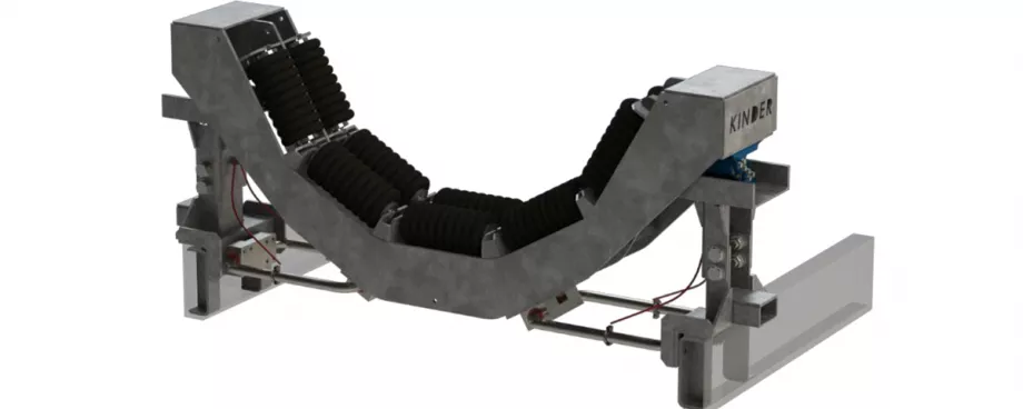
The last belt support system installed by the client was only in the interests of making the idler more reliable. A custom idler with 4 bearings (2 in each end) and custom frame fabrication was designed and installed resulting in a high stiffness system. Most of the frame was as per the 10-roll PROK series
59 ‘jack down’ idler frames, retaining the original ‘jack down’ feature for easy maintenance. Modifications include additional plate to increase transom stiffness, brace plate across the two transom plates, roller support bracing and an upgraded foot mount with larger M20 mount bolts (Fig. 23).
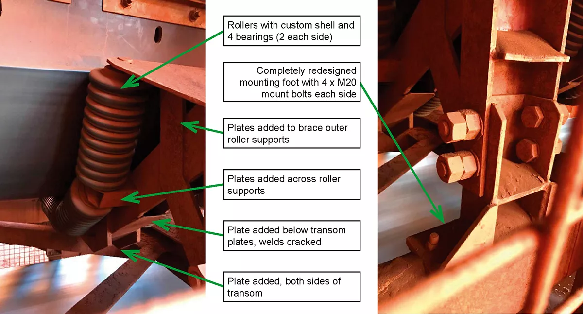
By stiffening the transom, all the load was placed on the belt, resulting in severe top cover damage. The client found the frame was still able to flex through the trough section, causing welds to crack. Additionally, as the four bolts are inline, the heads would eventually snap off, leaving the frame unsecure until the next available shutdown. Rollers had fair reliability, however the mount slot they sit in elongate resulting in an inconsistent belt profile, opening skirt gaps.
All trialled products suffered from poor reliability and did little to protect the belt. A new chute system would have been costly due to the current layout. What was needed was belt support with additional dynamic travel and therefore impact absorption to increase idler life and protect the belt.
4. Concept Design
4.1 Extra Heavy-Duty Dynamic Impact Roller Cradle
Kinder Australia initially proposed a conventional dynamic impact cradle designed to accommodate the customers rollers. Incorporating rollers was to reduce friction (Fig. 24). Given the chute width sat over the outer rollers, there was little room for a static wear bar or roller on the outside (Fig. 25). The trough had to be completely dynamic in some way. The centre trough was made much like a conventional dynamic system, able to move down to take impact, with the outer wing rollers placed on torsion springs that allowed a radial movement to take impact whilst reducing the allowable gap in the skirting. It also would have reduced an induced pinch point because of a dynamic centre trough with a static wing (Fig. 26).
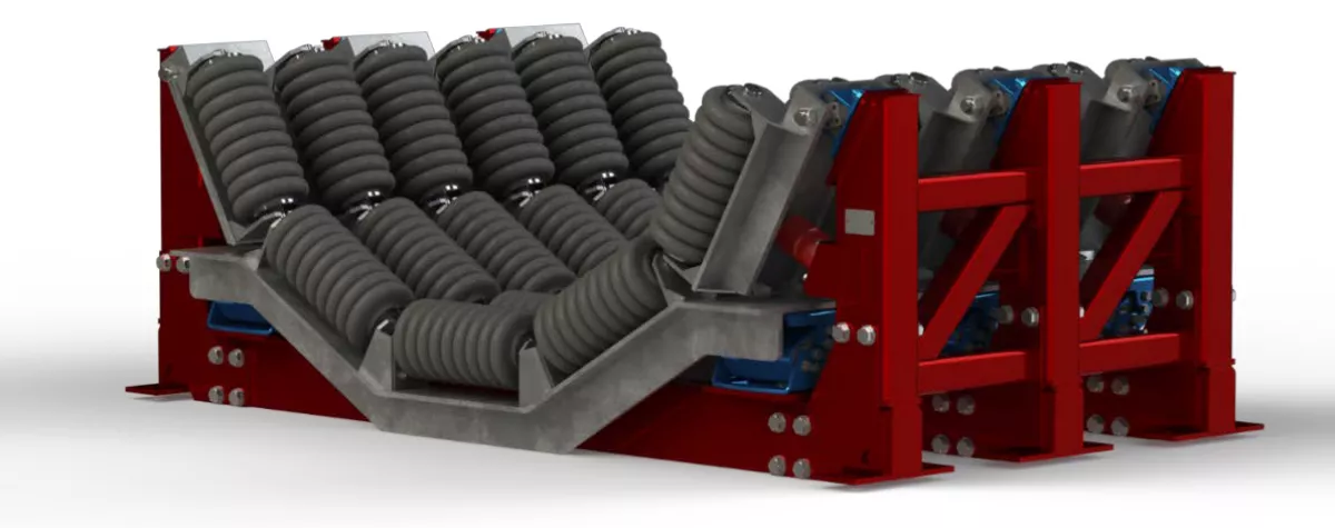
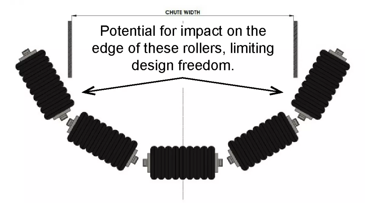
Fig. 25: Chute width layout across roller profile.
|
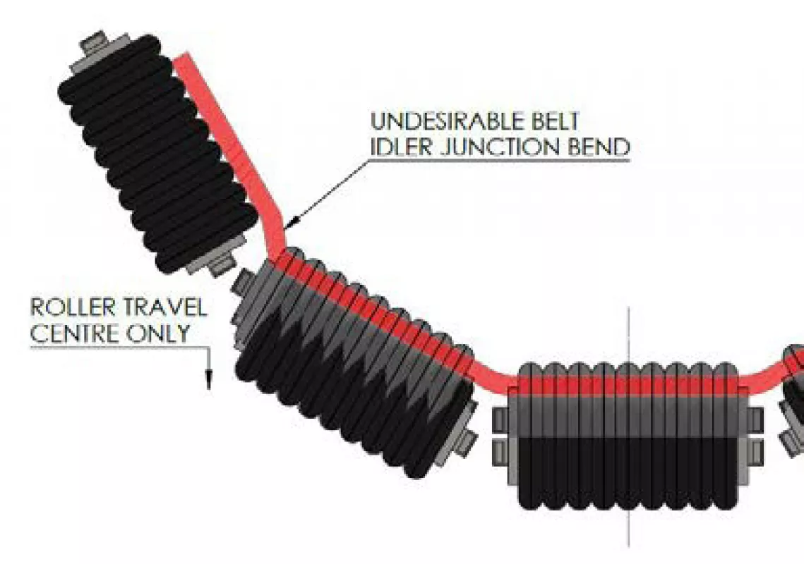
Fig. 26: Undesirable belt profile bend in a centre only deflecting dynamic system.
|
Whilst this system would have provided excellent belt support whilst minimising the compromise to skirting gaps, the system was expensive and didn’t allow easy access for roller changeout, something the client was very specific about.