
2.5 Dynamic Impact Belt Support Systems
A dynamic impact belt support system cradles the belt in much the same way as a conventional impact cradle, however the centre can deflect away in the presence of impact due to mounting on anti-vibration mounts.
| Advantages | Disadvantages |
|---|---|
|
|
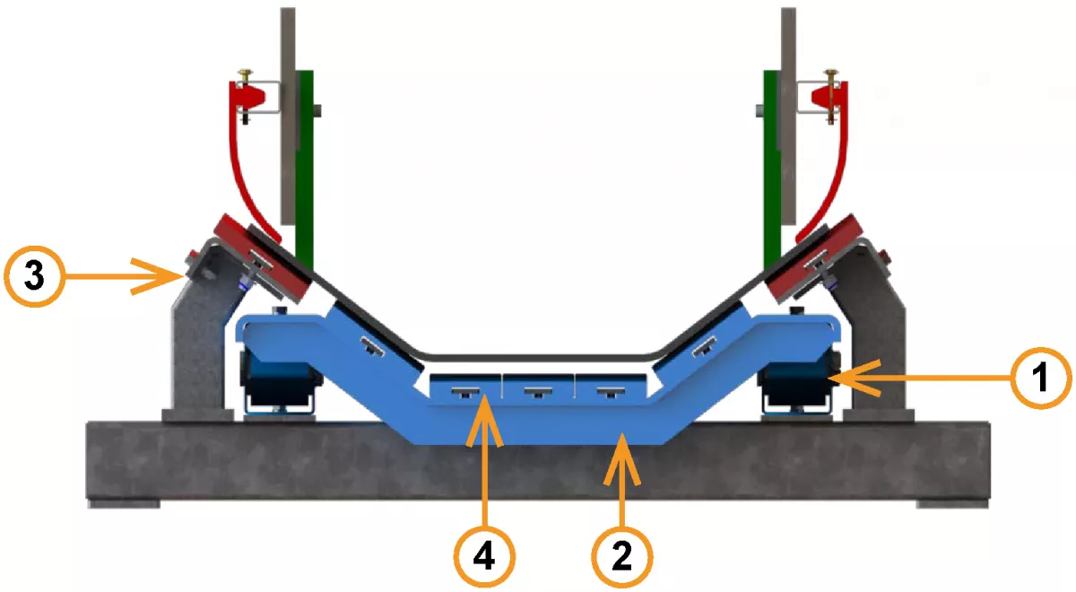
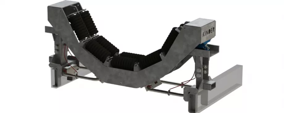
Fig. 13: K-Shield Dynamic Impact Belt Support System: 1) Energy absorbing anti-vibration mounts; 2) Dynamic trough suspended on anti-vibration mounts; 3) Fixed wings to maintain skirt gaps; 4) Low friction UHMWPE slider rails.
|
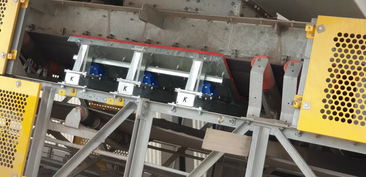
Fig. 14: K-Shield Dynamic Impact Belt Support System (1400BW).
|
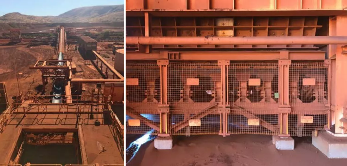
3. Case Study
The client’s application for which transfer failures occurred is a conveyor below a primary sizer processing iron ore directly from the mine (Fig. 15). Notable data from the system is the following:
- Belt Width: 1800 mm
- Tonnage: 5500 tph
- Bulk Density: 2500 kg/m3
- Maximum Lump Size: 450 mm
- Chute Drop Height: 6 m
- Belt Speed: 4 m/s
- Belt Specification: PN2000/2 18×7 Covers
- Chute Length: 6 m
Whilst the lump size for this system is extreme, when the primary sizer loses a tooth (a common occurrence), the lump size is even greater, due to a larger opening between crushing rollers. Fig. 16 shows the actual lump size was likely greater than 500 mm, with a trough width of 1500 mm and noting it is over a third of this width.
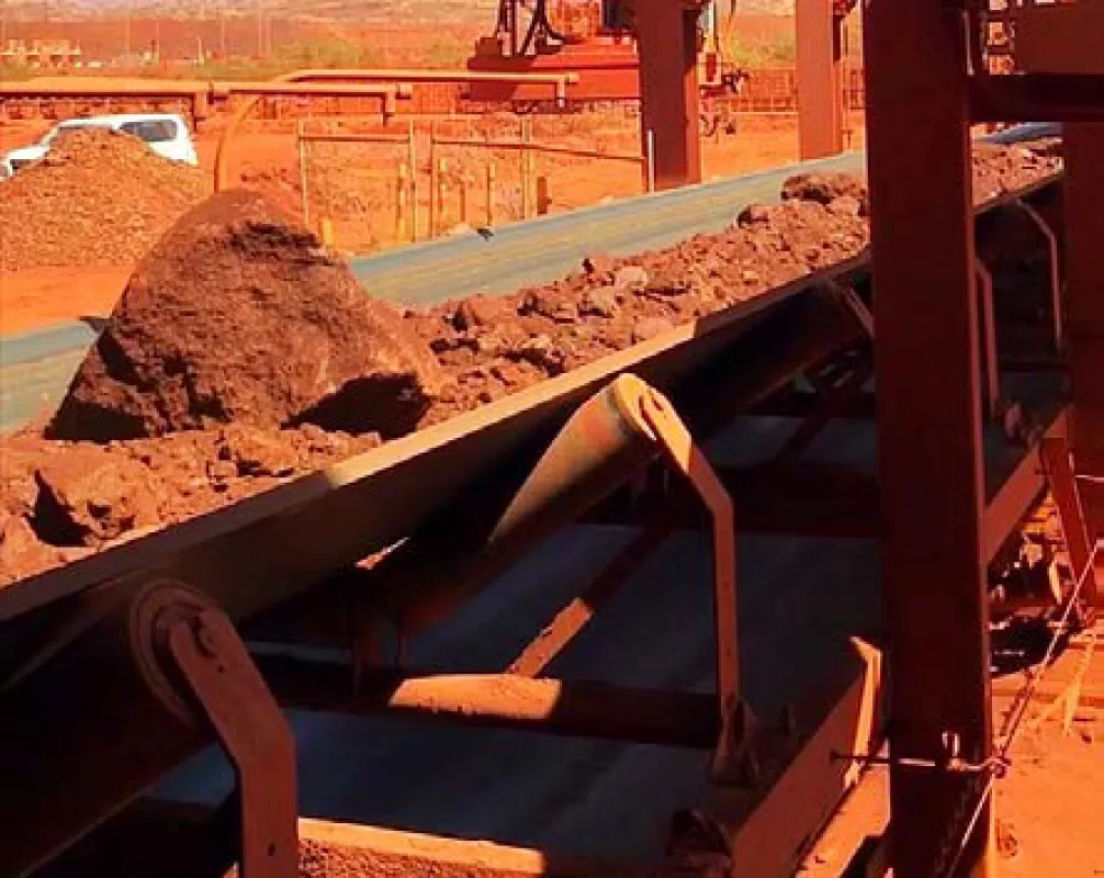
Fig. 16: Actual lump size observed.
|

Fig. 17: Severe top cover damage.
|
Originally specified with 10-roll PROK series 59 ‘jack down’ idler frames, the client has since tried several different products and modifications to the transfer area. These were only aimed at improving the life of the idlers and subsequent strengthening of components increased the impact wear to the top cover of the belt. Following the top cover damage (Fig. 17), the belt became difficult to clean and therefore track and keep spillage to a minimum, not to mention the inability to get more life out of the belt and system components.

