Re: Pressure Drop In Pneumatic Conveying
Dear pandaba,
Based on your limited data, the pressure drop is calculated as:
Horizontal:
with 1 m2 filter: pressure drop = approx. 0.17 bar
without filter: pressure drop = approx. 0.082 bar
Vertical:
with 1 m2 filter: pressure drop = approx. 0.22 bar
without filter: pressure drop = approx. 0.13 bar
The compressor conveing pressure can differ a lot by extra clean air piping and ambient and material temperatures.
The material is unknown.
Have a nice day
Teus ■
Teus
Re: Pressure Drop In Pneumatic Conveying
Thanks teus for kind reply.
My case is flow of fly ash in a pipe . I need some data on particle - particle and particle-wall collision for pneumatic conveying of flyash.
Thanks and regards
PP ■
Re: Pressure Drop In Pneumatic Conveying
Dear pandaba,
The material pressure drop in your system is only a small part of the total pressure drop.
The Solid Loss Factor, which you are asking for, is related to the calculation algorithm that you are using.
If I give you the SLF, I am applying, as 4.58*10^-12, it does not mean anything to you.
What you can do is calculating with your own program the SLF, which matches the given pressure drops in the previous reply.
Success
Teus ■
Teus
Re: Pressure Drop In Pneumatic Conveying
Hi Teus,
I am again coming back to this discussion. I want to know What is meant by solid loss factor. Can you please explain a bit more .
Also how to predict the pressure drop in horizontal gas solid flow. I found from simulation that the gas velocity, particle dia , density , pipe dia and loading ratio have high impact on pressure drop. Considering all these , how to predict pressure drop. ■
Re: Pressure Drop In Pneumatic Conveying
Dear pandaba,
The Solid Loss Factor is a product related value that, in a formula, accounts for the energy losses, due to inter-particle- and wall collisions.
The calculated energy loss is, through the appropriate formulas, expressed in a pressure drop.
The total pressure drop is the sum of all partial pressure drops (air, elevation, suspension, acceleration, product)
There exists no direct way to calculate the pressure drop in pneumatic conveying, as a calculated pressure drop is influenced by itself (Caused by the expansion of the air)
An iterating, numerically integrating, algorithm can solve this problem. (Approx. 45 Mb VB software)
Take care
Teus ■
Teus
Check My Software Solution
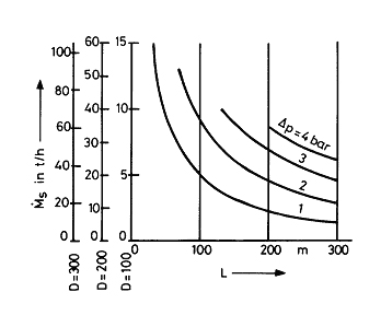
Hi there, have a look at my state diagram and software. It is an iterativ, numerical overall calculation, that apart from an interpolated estimated value for the pressure loss additional information provides. So, the given data belong to a dense phase conveying system near the instable transition area, and the pressure loss in a horizontal pipe will be around 0.11 bar. These results are confirmed by published field data of similar conveying lines. However, the question remains, how precisely the parameters can be read from the relatively rough state diagram.
These are the published data for a comparable conveying system: Material SiO2, 10 microns, bulk solids throughput 4000 kg/h, gas flow 100 Nm3/h, pipe diameter 65 mm, horizontal pipe length 30 m, pressure loss 0.3 bar (that meets exactly the calculated value).
Moreover shows the state diagram, that different conveying conditions are possible, so, for instance a lower gas flow at higher pressure loss. How can one say which the stable conveying conditions are? A good example for the wide variation of conveying conditions was published by
Krambrock, W.: Dichtstromförderung. Chem.-Ing.-Tech. 54(1982)9, S.793-803
The diagram shows a field of possible conveying conditions at maximum mass flow of bulk solids which lie on the left (upper) border of the state diagram.
Kind regards
ManfredH ■
Re: Pressure Drop In Pneumatic Conveying
 Originally Posted by pandaba
Dear Pandaba,
Please refer to my article "Theory and Design of Dilute Phase Pneumatic Conveying Systems" for calculating the pressure drop values. In this article you will find that the pressure drop due to the flow of solids depends upon the solids friction factor. Unfortunately, this value has to be determined from actual test data for this solid, there is no analytical method available for its precise calculation. I can give you an approximate value if you send me a small sample.
Regards,
Amrit Agarwal
Pneumatic Conveying Consulting
polypcc@aol.com ■
Are Friction Factors In Dense Phase Conveying Really Needed?
Originally Posted by Amrit Agarwal
Dear Amrit,
the state diagram, developed by me, does not use friction factors for the calculation of pressure losses, especially in the dense phase conveying of fine materials which are easy to fluidize. As the diagram indicates, is the main factor in such cases the state of the turbulent gasflow and the energy, that is provided through turbulent eddies and pressure gradients, for fluidizing a particular mass of bulk solids, that is thereby kept moving. Published field data show, that even moist sand of 200 microns, that is most likely considered for a cohesive material, fits in the state diagram, but with a very low gas flow rate at high pressure loss (plug conveying?!). For this reasons I am not sure whether at least in my diagram a friction factor is really needed. It is possibly a hidden parameter indicating stable conveying conditions or so.
Kind regards
ManfredH ■
Re: Pressure Drop In Pneumatic Conveying
Hi all
I have a requiremnt to fluidize coffee and the only information I have is physical properties of coffee.
I have assumed the drag co-efficient of coffee as 0.1(assuming spherical beans), and calculated the terminal velocity.
But I have no idea regarding the pick-up velocity or the required pressure drop to convey or fluidize coffee.
I would really appreciate if anyone can suggest the procedure or a book which can help me more.
Regards
Vineet ■
Re: Pressure Drop In Pneumatic Conveying
Dear Vineet,
I have a requirement to fluidize coffee and the only information I have is physical properties of coffee.
I have assumed the drag co-efficient of coffee as 0.1(assuming spherical beans), and calculated the terminal velocity.
Determining the terminal velocity of a particle (bean) is indeed the first step to do, when designing a pneumatic conveying installation.
Then the required air velocity can be assumed to be approx. 5 to 7 times the suspension velocity under atmospheric conditions.
Based on the required capacity and conveying length (vacuum conveying or pressure conveying), a pipe diameter is chosen.
From the chosen pipe diameter and atmospheric air velocity, a compressor displacement is chosen.
The pneumatic conveying installation calculation for the first assumption is then executed.
Based on the outcome of that calculation, a new installation is determined (bigger or smaller diameter), until the desired result is reached.
It is not advised to perform a pneumatic conveying installation yourself, especially if you haven’t done this before.
A well know supplier is a much safer way to go.
Not only the calculation, also the technical execution of the components is a challenge, which should not be underestimated.
I would really appreciate if anyone can suggest the procedure or a book which can help me more.
There are books and free calculation spreadsheets, however, I doubt whether they are safe to use for inexperienced designers.
Studying pneumatic conveying books and trying to design an installation, probably takes too much time.
Success
Teus ■
Teus
Re: Pressure Drop In Pneumatic Conveying
Originally Posted by Teus TuinenburgDear Teus
Thanks for the information. i totally agree that i should probably take the support of a vendor for installation. But, however, the situation right now asks for me to calculate the required pressure drop and air flow required because the solution given by vendors is not upto mark. I do have some theorotical base, but, that does not seem to help me when it comes to bulk-material. At present my biggest concern is, knowing the bulk-density of the material and required material flow rate, what all should i consider while calculating the pressure drop and required fan specification.
Thanks in advance
Regards
Vineet ■
Re: Pressure Drop In Pneumatic Conveying
Dear Vineet,
the solution given by vendors is not up to mark.
Communicate your concerns with those vendors. If they cannot convince you of their skills, look for another vendor.
At present my biggest concern is, knowing the bulk-density of the material and required material flow rate
Bulk density is of importance, especially in the bends and when sedimentation occurs.
More important is the particle density and the particle size (distribution), as these determine the suspension velocity.
The required material flow rate is something you have to decide yourself, based on your process requirements.
what all should i consider while calculating the pressure drop and required fan specification.
For the pressure drop, you have to calculate:
-pipe geometry (horizontal length, vertical length, number of bends, diameter)
-intake pressure drop
-acceleration pressure drop (depending on solid loading ratio)
-suspension pressure drop (depending on solid loading ratio)
-material pressure drop (depending on solid loading ratio)
-gas flow pressure drop (air or nitrogen)
-filter pressure drop
-gas velocities
-material velocities
-heat exchanges to determine the influence on the gas velocities
-gas losses in case of a rotary lock feeding
-gas compressor characteristics in terms of flow=function(pressure)
Opting for a fan, the calculation becomes even more complex, as the fan curve is far from straight and also the pressure range of a fan is very limited.
Calculating a pneumatic conveying system is rather complex, as all the variables are influencing each other.
BEGIN:
gas temperature influences gas volume
gas volume influences gas velocity
gas velocity influences particle acceleration
particle acceleration influences particle velocity
particle velocity influences material pressure drop
pressure drop influences gas temperature (expansion) and gas volume
BACK TO BEGIN
A pneumatic conveying calculation begins with two input parameters:
Capacity and pressure
One calculation with two unknown variables cannot be solved, unless an iteration algorithm is applied, whereby one of the variables is set and the other is calculated.
The iteration ends when the output matches the input parameters.
Nowadays, a computer is indispensable.
Take care ■
Teus
Re: Pressure Drop In Pneumatic Conveying
Originally Posted by Teus TuinenburgDear Teus
Thanks for taking out the time and explaining the details. I sure am far from designing it with that accuracy.
However there are a few terms which I as an engineer would like to know.
First of which is, pick-up velocity. How do I calculate it?. As I have earlier told, my product is coffee beans with bulk density 500 adn 300 kg/m^3, in green and roasted condition respectively.(Average particle diameter 7mm). Flow rate required is 1.8 tonnes/hr.
Second, the pressure drop that we calculate along the line, is it the same pressure drop that my fan should supply(I'm not designing the fan, but I have to tell my vendor what pressure drop I require). If not, then what is this pressure drop calculated for?
Appreciate your help on this
Thanks in Advance
Best Regards
Vineet ■
Re: Pressure Drop In Pneumatic Conveying
Dear Vineet,
For estimating the pick-up velocity, it is necessary to know (or measure) the suspension velocity of the particle under atmospheric conditions.
The suspension velocity of a particle is depending on the particle size, particle shape and particle density. Particle size and particle shape determine the particle drag factor. The particle density determines the particle weight.
Equalizing the particle weight with the particle drag force gives the suspension velocity.
Then, for the particle beans of 7 mm, the required air velocity can be assumed to be approx. 2 to 3 times the suspension velocity under atmospheric conditions.
The estimated suspension velocity of the coffee beans is approx. 12 m/sec under atmospheric conditions, resulting in a pick-up velocity under atmospheric conditions of approx. 25 to 30 m/sec.
If the pick-up location has gas conditions, different from atmospheric conditions, the suspension velocity and the gas velocity have to be corrected.
Second, the pressure drop that we calculate along the line, is it the same pressure drop that my fan should supply(I'm not designing the fan, but I have to tell my vendor what pressure drop I require). If not, then what is this pressure drop calculated for?
The pressure drop along the line is built from the resistance of the pipeline and depends on the chosen configuration.
-vacuum system or pressure system
-gas type (air or nitrogen)
-horizontal length
-vertical length
-number of bends
-pipe diameter
-altitude above sea level
-ambient temperature
-filter size
-etc.
For a chosen configuration, the pressure drop is calculated and based on this calculated pressure, a compressor type is chosen.
If the calculated pressure is considered too high, the calculation is repeated for a larger pipe diameter.
In case a centrifugal fan is applied, the pressure curve of the fan has to be considered in the calculations for partial mass flows of coffee beans.
Be aware that a centrifugal fan has an increased air flow at low pressures, causing very high velocities at low pressures.
The coffee beans might be damaged at low capacities.
At high pressures, the centrifugal fan has low air flows, causing the velocity to become lower tan the pick-up velocity and choking may occur.
Second, the pressure drop that we calculate along the line, is it the same pressure drop that my fan should supply(I'm not designing the fan, but I have to tell my vendor what pressure drop I require). If not, then what is this pressure drop calculated for?
The pressure drop is calculated for the compressor choice.
If the pressure drop is chosen, then the pipeline diameter and airflow has to be calculated, to match that pressure drop
Have a nice day ■
Teus
Re: Pressure Drop In Pneumatic Conveying
Dear Teus
Thank You once again for the help.
I have one more question now
I want to know how to theorotically calculate the pressure drop and reduction in velocity, in flow over a helical path. (The flowing material is a mixture of air and solid particles).
A study material would be of great help too.
Can anyone help me on this?
Thanks in advance
Vineet ■
Re: Pressure Drop In Pneumatic Conveying
Dear Vineet,
Have a look at:
http://www.criba.edu.ar/cinetica/sol...wal%202005.pdf
Best regards ■
Teus

Pressure Drop in Pneumatic Conveying
Pressure Drop in Horizontal & Vertical Conveying
My case is as follows:
Dia of pipe : 53mm
Length of pipe : 5m
Density of solids =2530 kg/m3
air mass flow rate = 0.0324kg/s
solid mass flow rate = 1.2184kg/s
Particle size = 30 micron
I want to find the pressure drop for this case in horizontal and vertical flow. Can anyone tell me what are pressured drop values . I want to do numerical simulation and compare the results.
Thanks
Regards
PP ■