

Grizzly Feeder Pivot Base Positioning
Hello Canuck1: Typical setup on standard electric motor or variable speed drive on a Brute Force Vibrating Grizzly Feeder TYPE OF UNIT is:
Looking from the Feed End of VGF towards the Discharge End of the Feeder
- Motor located on the discharge end Shaft of the two shaft VGF closer to the discharge end.
- Motor would be operating in a DIRECTIONAL ROTATION or towards the discharge end
- This would have the motor pulling downward also towards the discharge end keeping the belts tensioned while doing so.
- If we took the motor and installed it on the FEED END SIDE, you will have a situation where the MOTOR actually tries to climb up the belts to a point where it cannot, then it DROPS back down and tries again. This eventually super stretches the belts and then we have another problem involving slippage, reduced RPM, and eventually replacement of the belts. All of this action is not swell for MR PIVOT BASE either.
The pivot base MUST be setup correctly.....so as to NOT LOCK the base down with the vertical hold down rod and bolt system. If we LOCK it down.......it is no longer a PIVOT BASE but, a stationary base and the big weight of FEEDER will in fact ........RIP it off the RODS eventually.
RELATIONSHIP angle of motor to drive shaft....GIVE or TAKE 45 degree angle.........all manufacturers will actually have a range to mount the motor so it works properly. FOR EXAMPLE: directly below the feeder drive would not be a choice or desirable.
hope this helps.....
George Baker - Moderator ■
Re: Drive Motor Position
Dear Mr. Canuck 1,
The problem mentioned by you is of very specific nature difficult to visualize and comment. It seems that, you are referring to belt drive from stationary motor to rotating unbalanced mass. In this situation, theoretically the motor should be placed in such a manner that there is least dimensional effect on belt due to oscillation stroke of the screen i.e. such ideal location could be belt at right angle to oscillation motion.
Regards,
Ishwar G Mulani.
Author of Book : Engineering Science and Application Design for Belt Conveyors.
Advisor / Consultant for Bulk Material Handling System & Issues.
Email : parimul@pn2.vsnl.net.in
Tel.: 0091 (0)20 25882916 ■
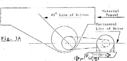
Maybe A Picture Will Help
I am attaching a general arrangement drawing of my motor base and vibratory feeder configuration. I hope you are able to make it out clearly, Figure 1A most closely resembles my current setup.
This configuration has worked well for nearly 15 years, but since replacing the original 30hp motor with a 30hp Torspec drive (bigger, heavier), I have broken 2 output shafts within one year.
The only differences between this drawing and our actual setup is our vibratory mechanism looks a little different (an oval housing with two shafts side by side in horizontal plane) and the drive belt is connected to the shaft on the grizzly, or discharge end, furthest from the motor. We are also using coil springs to prevent motor rebound on startup, minimal tension.
Any suggestions?
Thanks
Attachments
■
Re: Drive Motor Position
Dear Mr. Canuck1,
As informed by me in my earlier reply, the ideal location of the stationary motor is to have belt at right angles to the oscillating motion. If you see mathematically or graphically, you will observe that such position will make minimum affect on the variation in belt length during one oscillation cycle. The variation in length is square-root of (belt center to center distance square) + (oscillation stroke square). Now looking at your arrangement you have shown, if the drive motor is towards discharge side, the belt and oscillation stroke will be closer to right angle situation.
In your present case, it will shorten the belt life and will also put more fluctuating load on shaft in response to belt stretch and contraction. Please check the magnitude of this fluctuating load in combination with steady load and see whether this could be cause. It is essential that this should be examined considering oscillation stroke during starting, stopping, empty running, etc. and consider the highest magnitude of stroke. In some of the screens, or vibrating feeders, such stroke could be 4 to 5 inches during certain stage of operation. Use the modulus of elasticity of all belts together to decide the fluctuating load. The variation in stroke what you will be observing will be with respect to the constrain by the belt and that is the load occuring.
Regards,
Ishwar G Mulani.
Author of Book : Engineering Science and Application Design for Belt Conveyors.
Advisor / Consultant for Bulk Material Handling System & Issues.
Email : parimul@pn2.vsnl.net.in
Tel.: 0091 (0)20 25882916 ■
Torspec Variable Speed Motor
Please refer to actual VGF DRIVE PIC.....FOR Reference....hoping this is helpful.
Our rule of the thumb for motor sizing.........generally is to jump one motor size up....if going to VARIABLE SPEED type motor.
We find if we use 30 to 30 OR one to one....we have trouble starting up the VGF normally........
SIZE OF MOTOR; We would normally use twice the motor size needed........for starting the unit from a DEAD STOP than we need to actually RUN the VGF ....this applies to screens as well.
On startup we are pulling with the heavy side of the shafts down or a six oclock and need lots of torque to pull over 12 o'clock position .........AFTER we get over the 12 position.......we are a piece of cake.........we are running.....and no problem.
GEORGE BAKER
Attachments
■
Great Drawing
Thank you very much for the very helpful drawing.
I recognize that the motor being mounted 90 degrees to the line of action is desirable, but my feeder was factory assembled to be driven from the other side of the vibrator. Hewitt-Robins (and others) built many this style I have since discovered and they used an eccentric bushed driven shieve to reduce the effect of feedback to the motor/pivot base assembly. Ours had worked for so long with the original motor, that no-one thought twice about the effect of installing a much heavier drive in roughly the same position.
It was your drawing which gave me the answer. You indicate the motor shaft to pivot shaft offset should be around 1 3/4". Even on our original 30hp motor pivot base used a 3" offset. Wider than normal, but usable. We had to modify the original pivot base to accept the Torspec drive (longer wider and about twice the weight of the original 30hp motor). In doing so, we opened up the motor shaft to pivot shaft offset to nearly 8"! This despite the fact that the new drive was twice as heavy as the original 30hp motor!
The pivot base works like a 2nd class lever, by moving twice the weight more than twice as far from the fulcrum, we turned our pivot base into a fixed base. The base could not move upwards with the feeder as it was designed, and the output shafts broke.
Problem solved? I hope so, thank you again everyone for your input. This isn't the first time this forum has worked for me!
Sean Gibbs
Victoria, BC
PS can you do anything about the hockey lockout? ■
Motor Base Problem.....Solved...
Hello Sean: I am glad that print worked somehow, someway for you. THANKYOU for the positive feedback as usual - appreciated.
Nowwwwwwww about the HOCKEY LOCKOUT.......I will call my buddy DARRYLL SITTLER to see if he can help.......He is still playing right???? :>))
See Ya.......SLAPSHOT GEORGE......."He Shoots.......He Scores"
Sean: do you know my buddy Cliff out there?? Vangara? ■

Drive motor position
Can anyone tell me the optimum position for the drive motor (actually a Torspec variable speed drive) to power a vibratory grizzly feeder on a portable jaw plant? I am getting conflicting information from different sources, one saying the motor should be mounted on the discharge side of the feeder and the other saying it should be on the feed end. The feeder itself is a standard two shaft Hewitt-Robins type eliptex feeder with a 45 degree timing angle. It is mounted horizontally on standard steel coil springs with an underslung vibrator. The motor base is a conventional pivoting base type.
What is the correct relationship between the drive motor and the vibratory mechanism? The others I have seen are mounted on the feed end of the feeder approximately as far below the vibrator as they are away from it. ■