Screener
If you could provide some images that would help a lot.
If your trailer carrier is not very heavy the screen resonance may be
overpowering the mass of the trailer.
Did you consider mounting the screener on a set of airbags for support and
resonance cancellation? ■
Re: Balancing A Four Bearing Single Shaft Screen
 Originally Posted by lzaharis
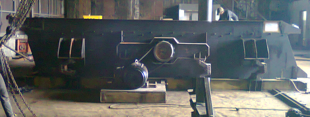
href="showthread.php?p=74329#post74329" rel="nofollow">
When I test run the screen, the wire cloths haven't been installed yet (but I think there is no issue in balancing the screen without the wire cloths) and it is set horizontally (when it is supposed to be inclined). The screen is mounted on a pair of WF 250 beam, and is laid on the ground without being bolted.
I haven't considered mounting it on airbags support, but then, even without the airbags support the screen runs smoothly (with the arms aren't fix welded to the WF 250). But I am not sure whether the screen is already in balance since it can also run unbalanced but the mounting support (rosta oscillation mounts) is dampening the vibration to the structure (due to unbalanced condition) and making the screen looks like balanced. One of the main problems is that I do not know what an unbalanced/balanced condition of a four bearing single shaft screen looks like, maybe you have reference where I can see videos of such screen running in balanced/unbalanced?
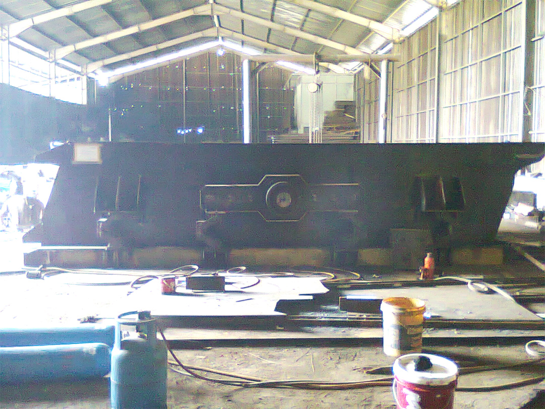
Anyway, below are the photos attached. Thank you for the advise, Izaharis.
Regards,
Chris
href="https://forum.bulk-online.com/attachment.php?attachmentid=32595&d=1334984935" id="attachment32595" rel="Lightbox74338" target="blank">■
Screener
About your screener,
No amount of suspension is going to solve your problems if the welding is not square.
did you do the welding in a jig(secure frame to prevent twisting or wracking)
for each corner-if not your doomed.
Do not expect to balance your screener without the screen cloth or screen sections!!!!!!!!!!!!!!!!!!!!!!!!
If the welding and box are not square no amount of work or air bags is going to correct
it prior to running ore over it.
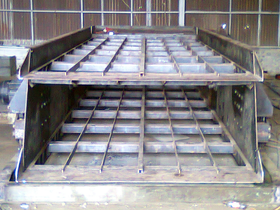
The picture of the screener at the discharge end is troublesome as there
is no interior cross bracing or support tubing and the top deck looks to be
sagging in the center from my perspective.
If the side plates are not of the same weight thats problematic.
Your screener does not appear to be suspended by the rubber mounts as
there is no clearance between the end lip and the steel underneath it that
is A BIG NO NO.
■
Re: Balancing A Four Bearing Single Shaft Screen
Now that you mentioned about the sagging of the cross member, I wil checked them asap, And have the chassis support under the Lip modified. We have done our best to weld the box as 'square' as possible, but if it is as you said, then we still have to continue until the end since we already put quite an effort here.
About the cross tube bracing at the end discharge, I agree with you though, but why there are some manufacturer (tyler, terex, etc) do not use such bracing...i wonder
The side plates, yes, but unfortunately, in my country, it is very difficult to acquire good materials and good workmanship.
Anyhow, izaharis, maybe you can help me describe how a four bearing single shaft is balanced? And how it looks like under balanced or not balanced condition, at least woth this type of setting..
Thank you for your input...maybe I should really just buy an F-class screen from Tyler..sigh...haha
Regards,
Chris ■
Screener
Originally Posted by virtu86
Hello Chris,
Even if you buy the smallest F class screener you will be better off; saying that a
horizontal screener is an even better less troublesome screener.
About your screener.
Have you measured the diagonal distance- Meaning opposite corner to opposite corner(upper right corner to lower left corner) and (Upper left corner to lower right corner).
If the distance is not identical it is not going to work unless you remodel it into a horizontal low speed screener and install the interior support tubing. ■
Re: Balancing A Four Bearing Single Shaft Screen
Hi izaharis,
The diagonal distance is the same. Could you describe what are the troublesome factors about this type of screen? I could only think about the maintenance, especially when we have to replace the inner bearing, it woukd be quite troublesome. Our quarry is currently using an inclined two bearing single shaft screen though...with unbalanced weight..it is much simpler...
It happens that I saw the f-class tyler brochure in the internet, so i do a little research...read in the vsma too, mentioning that this type of screen has its stroke independent with the material feed load, hence the tyler saying it heavy duty?? And start/stop smoothly...that picked my interest as i have never seen such screen before and in my country, this type of screen is very very rare...no quarries that i know (about 20 quarries) use this type of screen.
So before taking out quite a sum of money to purchase from the manufacturer, i decided to do a 'fun' project...
But anyway, thanks a lot for the knowledge shared...
Regards,
Chris ■
Screener
Originally Posted by virtu86
The troubles with "any" suspended screener for quarried aggregates and minerals are many over time:
1. side plate cracking at bearing holes.
a. broken welds at electric motor mounts.
b. broken corner welds.
c. loss of weight tape for balancing.
d. fines build up in screener affecting balance.
e. screen blinding affecting balance.
f. blown oil seals if used.
g. undetected bearing damage/failure.
2. screen cloth breakage
3. screen cloth mount breakage.
4. mounting rubbers plugged with fines and transmitting
resonance rather than absorbing and shedding it.
These are a few of the reasons I like air bags for suspension
over wire rope or rubber isolators in my opinion.
As for me:
The simpler the better-that why I like the Bradford Breakers as they
can screen and break at the same time and have none of the problems listed above. ■
Balancing A 4 Bearing Screen...
Hello Chris: some comments, firstly, you picked a very hard screen unit to reverse engineer and copy. That company has been doing this for over 100 years and gone thru all the design pains....
The problems could be numerous, which is common with vibrating screen design stuff:
1. I copied this sentence from your LINK: "Steel counterweighted wheels with calculated weights for proper balancing"
2. I DID go thru that whole link you sent, that you worked off of and it was set up for grids for polyurethane or rubber sections.....i think i saw you are using wirecloth? that is a different weight setup and a different balancing calc.
3. I read that you HAVE NOT INSTALLED the WIRECLOTH while testing. All vibrating equipment must have the selected MEDIA, rubber, poly, wirecloth, cast OR whatever installed on the machine at time of test run in to ensure the balance of the vibrating body is in fact correct. We insist our customers send in their wirecloth or whatever to have it factory installed so we can guarantee it is balanced with the media installed.
4. a properly balanced machine will in fact SHOW SIMILAR SHAPED CIRCLE IMAGES ON ALL 4 CORNERS AND At both sides at the CENTRE position over the shaft.
5. Izaharis, my buddy was quite correct in his comment, of JIG WELDED to ensure complete absolute SQUARENESS of the members or you will never balance and most big vib screen mfrs STRESS RELIEVE by oven and/or TIGER TORCH after all welds are completed to ease up the tightness of the welds. Can you a sonic stress relief gun also.
6. good luck for now...
george baker - moderator
[/U]
Originally Posted by virtu86■
Re: Balancing A Four Bearing Single Shaft Screen
Chris
You have the screen running close to natural frequency - most likely possibility. You should do an impact test to determine frequencies you can run the screen at.You can also try to change running speed and see what happens but then you trying your luck.
Regards
Ziggy Gregory
www.vibfem.com.au ■
Re: Balancing A Four Bearing Single Shaft Screen
Dear George,
Yeah, you are right, more than 100 years actually...
Anyway, here's my big question:
What i understand about how a four bearing single shaft screen works is that it works like a crankshaft of an engine. So, the screen actually moves in a constant circular motion with a stroke diameter equals to the eccentricity of the shaft designed. The part of the shaft which is in the main screen body (held by 2 inner bearings) is plain, and the eccentricity part is designed immediately after the shaft part leaves the inner bearing area and held by the outer bearings. Hence, the centerline of each the inner and outer bearings is on different plane with each other as far as half the stroke diameter (in my case, 4 mm, since the stroke is designed to be 8 mm).
The simple design is such that the outer bearings uses simple plummer block fixed/bolted on the main frame (e.g. Wide flange or H beam). The screen body is then mounted on a suspension system (at four corners, could be spring coils, rubber mountings or rosta oscillating mounts; i use the latest). But the problem here is that if you run the screen immediately, the whole screen will vibrates erratically and jumps around like a frog SINCE the nett resultant of the moment of the screen body is equal to the screen weight itself, in other words, the whole screen body acts like a counterweight to the rotating shaft (which is the total weight of the body x the eccentricity distance, i.e. 4 mm). Certainly this cannot work, that is why we have to 'BALANCE' the screen by counter acting the moment delivered by the screen body so that the nett resultant of the moment of the overall vibrating system is zero, in other words, the screen will vibrate due to only the eccentric mechanism designed on the shaft and not because of the unbalanced condition. So, this balancing is done by putting a counter weight between the outer and inner bearings on both sides. The counter weight is set to be 180 degrees from the eccentricity, which means when the screen body throws itself in clockwise manner, the counter weight set oppositely will cancel the moment delivered by the screen body. The weight of the counterweight is determined by calculating the distance from the centerline of the outer bearing to the center of gravity of the counter weight, and then you can design physically the shape of the counter weight. It is preferable to have the counter weight as slim as possible and as close as possible to the screen body, that means you will have a larger area of the counterweight.
I intentionally make a number of different thickness of shims to add additional weights to the counterweights (flexible design). This screen and its balancing is very similar to a jaw crusher (and cone crusher, vertically).
Taking reference from VSMA, since in practical, it is impossible to balance the screen perfectly, usually many manufacturers of this type of screen has the outer bearings mounted on rubber mountings in order to dampen the residual vibration due to the imperfect balancing. So, i assume that if the screen is ideally/perfectly balanced, there should be no vibration whatsoever transfered to the structures (since the nett resultant of the moment is zero).
But then, here i see that this f class tyler screen actually mounts both of its outer bearings on suspension system similar to the one used for the main body. Moreover, the outer bearing is not aimply housed with a plummer block, but is housed inside an extended arm where the suspension system can be placed further away from the center of the outer bearing. With such setting, i believe that eventhough the system is extremely unbalanced, the screen will only run like a normal two bearings single shaft screen (with an additional of circular motion due to the eccentricity of the shaft design). So it vibrates due to both the eccentric design and unbalanced condition. This is what exactly happens in my ase, i believe.
Since i do not know how a balanced four bearing single shaft scren looks like, i do not have a reference data. So, george, i 'think' what you mean by balanced is different from what i meant, your balancing term refer to the finishing step of the screen. Where what i am still wondering is the main concept of the balancing of the system (double eccentric shaft). And i am somehow certain that we are unable to balance the screen like what you meant since we are fabricating this screen with low quality of workmanship. But of course, at least i would be able to see the concept of how the screen works eventhough it will not run in a perfect way.
So, as i stated in my first post, when i test run my screen without installing the wirecloth, i simply want to know how the balancing actually works and looks like. And the type of screen media has nothing to do with the balancing (except its weight). But you have a point there maybe due to that i did not install the wire cloths, the main body has less weight than what it is supposed to be when in complete state, which ruins the balancing. As where there is a possibility that without the screening media and tensioning system installed, even without the whole counter weight additional shim weights added, the outer bearing system (including the whole weight of suspension systems and extended arm housings) has a bigger moment than the main body delivers when run.
Well, this is how i understand the concept of the balancing. Maybe i am wrong in many points. This is he most important part at the moment. All of the other imporant points or aspects of a good design can latter be improvised systematically (in my opinion...perhaps i am wrong?) with helps and advices coming from the more experienced/seniors in is forum 
As in the case to my actual problem, please refer to my first post.
Nobody has the video of this type of screen running, eh???
Anyway, thank you, george for your great input, i will certainly look for your advices on many aspects later on...hehe
Regards,
Chris ■
Re: Balancing A Four Bearing Single Shaft Screen
Dear ziggy,
Thanks for the input. But how can i know that the screen is actually running in its natural frequency? What is the distinct characteristic of a screen running in its natural frequency? I mentioned that the screen vibrates eratically, perhaps i used the word wrongly. The screen vibrates eratically in a manner that the whole screen and the chassis it mounts on jumped off the ground continuously due to that the chassis in not bolted to the ground and that due to the suspension system, the whole screen jumped off. So what i meant is that the stroke becomes bigger as the speed increases but i did not see how the stroke goes till the end (whether it reduces gradually until it reaches some point or operational speed or that it stays constant at certain point or that it grows bigger and bigger) as i was afraid the whole screen would be damaged.
But if it is as what you have said, what is the best and/or most economical solution?
Thanks.
Regards,
Chris ■
Screener Etc
Originally Posted by virtu86
Not all screens are the same or operate the same, some screens have an elliptical orbit and throw material uphill as it is cascading down.
Screens must be balanced and all parts must be level when they are constructed and with wirecloth installed, if the welds are not right and jigs are not used NOT GOOD.
How on earth can you compare a jaw crusher with a massive flywheel, V belt drives, toggle and wear plates to a screener???????????? These are two totally different animals living on the same farm.
Jaw crushers have driven shafts that are dynamically balanced just as the same jaw crushers flywheels and V belt pulleys that are connected to it.
The stresses are totally different and active as it is breaking material rather than sorting a mass flow of material
that overflows with the oversize material.
How can you compare a screener to a cone crusher?, you cannot, you can have anywhere from two to X number of slip fit bearings in a stack in a machined cavity that is stationary with an oil bath lubrication method in Spokanes case specifically. The driven and drive pulleys and center shaft are dynamically balanced as well.
It takes a lot to build a screener just like a tracked mining shovel. ■
Re: Balancing A Four Bearing Single Shaft Screen
Dear izaharis,
Yes, they are different animals living on the same farm, my mistake...i was actually referring in a general idea to the concept of dynamic balancing of the shaft of either jaw or cone crusher.
Anyway, thanks for the advice...
Chris ■
Re: Balancing A Four Bearing Single Shaft Screen
Chris
If you attach a small piece of paper at four corners and the centre of the screen and in the middle you should have pretty regular shapes(touch it with a pen when the screen is running) - most likely ellipsis in the corners an a circle in the middle. When you have the results please email it to me so I can have some idea what's going on. Please write to ziggy.gregory@vibfem.com.au - I did not get the message that you answered my post.
Regards
Ziggy Gregory
Thanks for the input. But how can i know that the screen is actually running in its natural frequency? What is the distinct characteristic of a screen running in its natural frequency? I mentioned that the screen vibrates eratically, perhaps i used the word wrongly. The screen vibrates eratically in a manner that the whole screen and the chassis it mounts on jumped off the ground continuously due to that the chassis in not bolted to the ground and that due to the suspension system, the whole screen jumped off. So what i meant is that the stroke becomes bigger as the speed increases but i did not see how the stroke goes till the end (whether it reduces gradually until it reaches some point or operational speed or that it stays constant at certain point or that it grows bigger and bigger) as i was afraid the whole screen would be damaged.
But if it is as what you have said, what is the best and/or most economical solution?
Thanks.
Regards,
Chris[/QUOTE] ■

Balancing a Four Bearing Single Shaft Screen
How to balance a Four Bearing Single Shaft Screen
Dear All,
I have a problem in balancing a Four Bearing Single Shaft Screen. I do not know how a balanced or unbalanced state of the screen looks like.
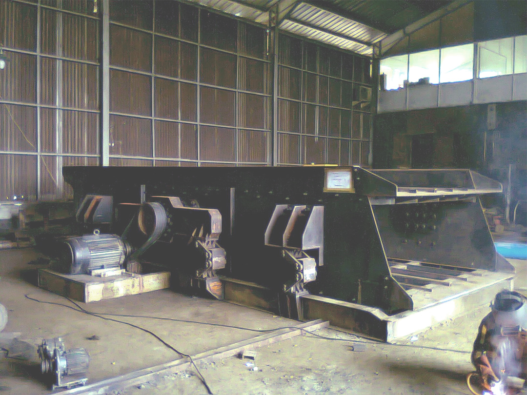
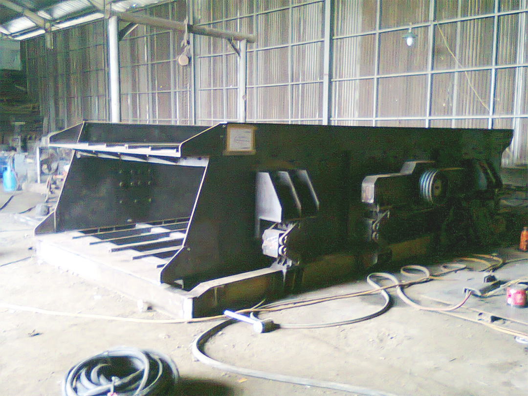
The screen is custom made similar to F-class Tyler screen (refer to http://www.wstyler.ca/pdf/techspecs...TechSpecs.pdf) where the outer eccentric bearings are inserted each into a bearing housing with an extended arm spanning a meter across left and right from the center point of the (outer eccentric) bearing. Each of the arm is mounted on two units of (also) custom made Rosta rubber oscillation mount.
The body of the screen itself is mounted on 4 Rosta rubber oscillation mounts, so there are 8 units of rubber mounts mounted to the screen in total.
Below are some information which I could provide:
1. Overall dimension: L: 6 m x W: 2.4 m x H: 1.5 m
2. Eccentricity of the shaft is designed to have a 8 mm stroke
3. The speed of the shaft is 860 rpm
4. Top deck opening is 25 mm
5. The screen is inclined (the angle is yet to be decided)
Problem is: When the screen is tested to run (the chassis where the screen and rubber-mounts mount on is not bolted to the ground), I observed that the arms vibrates with bigger stroke than the main body. Using a stroke card, I measured the stroke of the main body to be only 4.5 mm, and the stroke varies differently on each 8 end corners of both the side main body plates. Most importantly is that I cannot differentiate the state of balance of the screen as in my opinion the screen run smoothly at its operating speed. There is very minimal vibration to the chassis/structure which is not bolted to the ground. But seeing how the design of the arms where they are mounted on the Rosta rubber mounts, I only could think of another possibility that the screen is actually unbalanced and that the vibration is damped significantly by the Rosta mounts.
After that, I added more weight to the counter balancing weight, and the vibration behavior is similar to the first test, with only difference in the stroke which is 10 mm (roughly estimated since the stroke on each corner of the body varies quite significant), bigger than the eccentricity of the shaft design to have 8 mm diameter stroke.
Lastly, I welded both of the arm structure to the chassis so that the arm will not be able to oscillate on the Rosta mounts and that all the stroke driven by the motor via the double eccentric shaft will affect only to the main body. I did this since I have seen this type of screen with the outer eccentric bearing directly mounted on its chassis without any dampening device (and also to see whether the screen can be balanced with similar setting). The first trial is with all the additional weights on the counter balance removed leaving only the main plate. The result is the whole screen jumped 100 mm off the ground erratically, so we stopped it before the screen reached its operational speed.
And then we added more additional weight on the counter balance, the result is worse.
So, my main question is:
1. How to balance this type of screen
2. How a balanced Four bearing single shaft screen looks like in its running condition
3. What is the minimum tolerance in the balancing? Does it have to be perfectly/precisely balanced to run properly?
4. If the screen is unbalanced, I think that the screen vibrates like a 2-bearing single shaft screen driven by 2 unbalanced weight dampened by the Rosta mounts and has an extra point where it won't be able to be overloaded as the screen is driven with the eccentricity of the shaft design. am I correct or not?
5. Why is the stroke varies significantly on each corners of the main body? How will it affect the performance of the screen? I can only think that the Rosta mounts which we custom made simply SUCKS (the rubber elasticity/shore durometer of each rubber mounts aren't homogeneous enough) and that our overall workmanship is not competent enough in which the overall screen body structure isn't symmetrical. I can only think of these factors.
I really wish that someone (who has experience in this field) could help me or at least help me analyze this problem. Please advise.
Please do not hesitate to ask me for any details which is considered relevant to this matter but isn't mentioned in my post.
Thank you and regards,
Chris ■