Re: Optimisation Of A Pneumatic Conveying Line
Hi Stijn,
Are you sure that the material density of perlite is 221.8 kg/m3?
On wkipedia I find a specific density of abt 2.2, meaning a material density of 2218 kg/m3
Also, what is the bulk density of the perlite as that influences the pipe filling degree, certainly at high SLR
All for now
Teus ■
Teus
Re: Optimisation Of A Pneumatic Conveying Line
Dear Stijn,
More questions.
Pipe DN80 has an internal diameter of 83 mm (Area= 0.005398 m2)
Calculating tha airflow you use from 12.56 * 0.005398 = 0.06779 m3/sec
The air mass flow is 0.0869 kg/sec
Assuming an air density of 1.18 (25 degrC), this results in
a compressor displacement of 0.0869/1.15 = 0.07364 m3/sec (8.6% difference)
From what you already know, I understand that there is an existing system that does not work well.
If the RV can only run for a few minutes each time, that indicates a feeder problem in relation to pressure and rotor leakage. (Not an uncommon problem in pneumatic conveying)
Can you describe how it works and what capacity it reaches under which pressure drop?
Also important is to know the leakage through the rotary valve. There fore the (name plate) data of the compressor and the RV are necessary to know for a calculation.
Also have look at the articles in the bulk blog (4th button from the left at the top of this page)
All for now
Teus ■
Teus
Re: Optimisation Of A Pneumatic Conveying Line
Dear Stijn,
Using the preliminary design option in my computer program, I found the following results:
Input:
horizontal length 35.2 m
vertical length 31.3 m
16 bends
pipe inner diameter 83 mm
Perlite
particle size 30 micron
Material density 2218 kg/m3
suspension velocity 1.2 m/sec
Compressor displacement 0.07 m3/sec
Conveying pressure 3500 mmWC
Back pressure 1100 mmWC
pressure drop 2400 mmWC
Capacity 3.28 tons/hr
Calculated: the product collision loss factor (cwpfactor)
Output:
cwpfactor = - 1.15 * 10^-10
pressure drop material intake = 100 mmWC
pressure drop acceleration = 1523 mmWC
pressure drop elevation = 395 mmWC
pressure drop suspension = 527 mmWC
pressure drop air = 320 mmWC
pressure drop product losses = -547 mmWC
velocity begin = 11 m3/sec
velocity end = 12.4 m3/sec
The pressure drop for material intake + acceleration + elevation + suspension + air is more than the available pressure drop.
Therefore, the program calculates a negative product loss factor, “creating” the extra needed pressure drop to balance the calculated pressure drop with the available pressure drop.
As losses cannot create energy, the conclusion must be that the calculation indicates that the installation will not perform as required.
Checking the design and measuring the existing installation is necessary and advised.
Success
Teus ■
Teus
Extra Info
Dear Teus
Thank you for your quick response.
With 221.8 kg/m^3 i ment the bulk density of perlite. The material density is +- 1100 kg/m^3. I used the bulk density and the shape factor (=1) to determine the particle density of perlite: 221.8 kg/m^3 / 0.6 = 369.8 kg/m^3
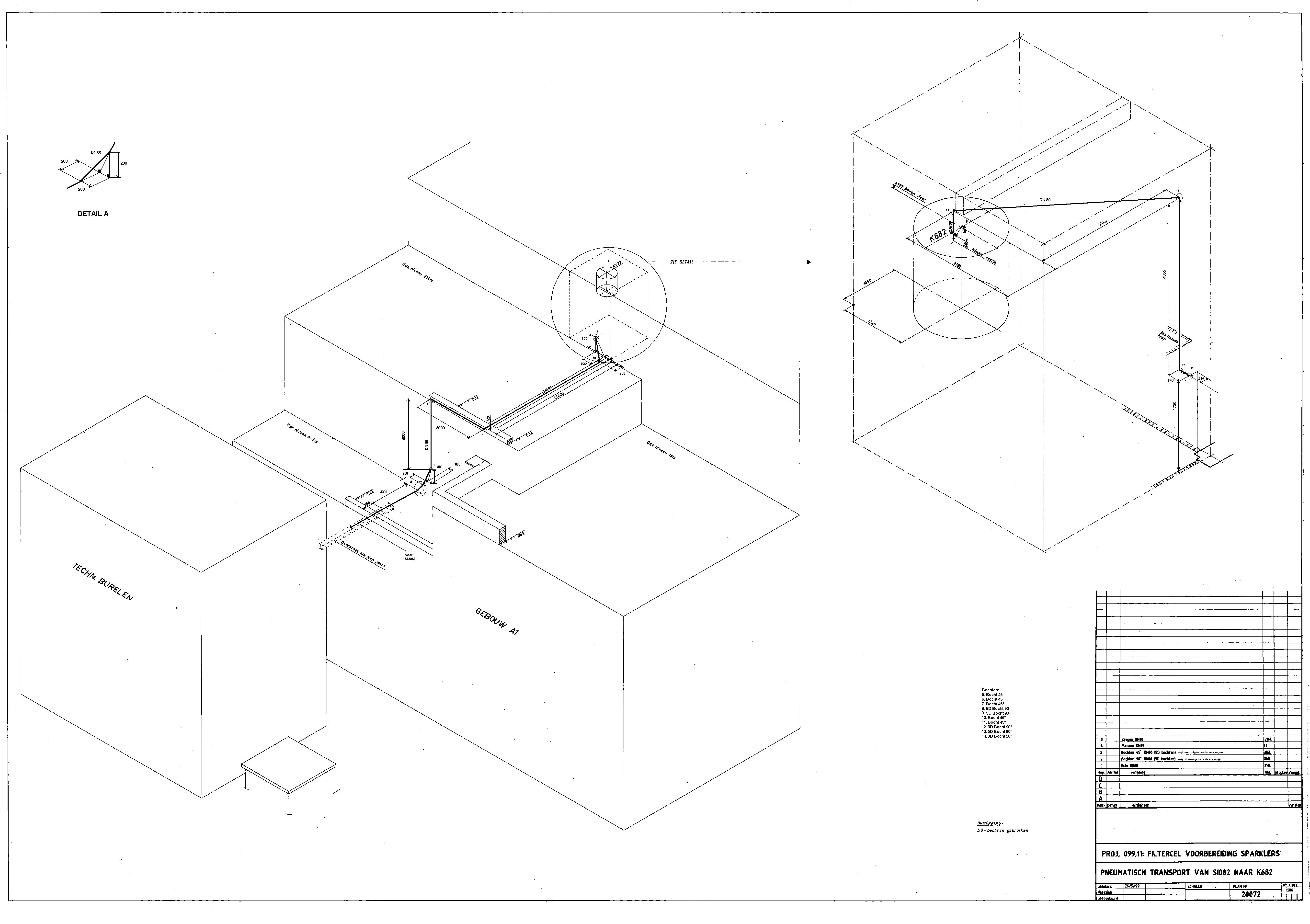
I’ve attached some files to clarify the problem. In ”linetorotaryvalve082” and “RV082” you see how line DN80 goes from RV082 (SL082) to vessel K682 with all the bends. “Pressurelinessilo082” gives a presentation of all pressure lines which are connected with the silo and the rotary valve. A pressure valve (PV-10072) adjusts the compressed air from 1.5 bar to 0.350 bar before it feeds the RV. The compressed air comes from big compressors elsewhere in the company, i don’t know the exact data.
Info RV:
- blow-through airlock
- open rotor (rotorcontent = 0.0138 m^3)
- marge between rotor and RV-house = 0.2 mm
- rotorlength = 0.30m
- rotordiameter = 0.28m
- rotorspeed = 0.35 turns/s (reduced from 23 turns/s)
- output ratio = 0.85 (theoretical)
- connectiondiameter to line DN80 = 107.9 mm (DN100)
- air mass flow at RV (9.2°C – DN80) = 1.686 kg/m3 * 0.0578 m3/s = 0.0974 kg/s
- solids mass flow at RV = 0.85 * 0.0138 * 0.35 * 221.86 = 0.911 kg/s
- SLR = 9.35
- capacity = 3280 kg/u
The RV runs only for a few minutes, but it can certainly run 3 times longer without problems.
3200 kg/u is the theoretical capacity, in practice there only arrives 20 kg/min of expanded perlite in vessle K682.
I’ve already proposed to install a RV which is a degree smaller because the actual RV is oversized. The SLR of this RV is 4.14 and the connectdiameter is 83.1 mm (DN80). Then there is also no blockage after the RV because the internal diameter becomes smaller (DN100 to DN80).
In “measurements” you can see where i did my measurements. Because vessel K682 and gas separator GW682 are closed vessels, i could only determine the air velocity after ventilator V682. I assumed that the pressure there is atmospheric. Then i’ve calculated the air velocity at RV082 with the gas law. I determined the pressure drop over DN80, so that i know the pressure in vessel K682 = pressure gas separator GW682 because there’s only a small horizontal pipeline between K682 and GW682. My solutions you can see in “results”.
I’ve already collected enough information to make a new track for this pneumatic line with use of the smaller RV. I had still one question: when you go from a horziontal to a vertical straight pipe, is it best to use a 90°-bend or 2 45°- bends shortly after each other? I dont know exactly what’s best for the reacceleration of the particles. I must also use special elbows because i thing this perlite belongs to geldart type C.
Thanks in advance
Stijn Gommers
Attachments
■
Re: Optimisation Of A Pneumatic Conveying Line
Dear Stijn,
I studied your installation drawings, but must admit that it is rather difficult for an outsider to figure out how it works.
Using the particle density, which is probably lower than the material density, due to the porosity of the perlite, the suspension velocity must be approx. 0.47 m/sec.
For a real performance of 1200 kg/hr, the calculated product loss factor becomes a positive value and amounts to 1.7372E-8 (Related to my calculation algorithm)
In relation to the lossfactor of other products, this seems a reasonable value.
The calculated velocities of 10-12 m/sec (23 times higher than the suspension velocity) are unnecessarily high.
The installation, which you are operating is a complex system and needs much more investigations and fine tuning than the forum members can deliver here.
I read in another thread that Mr Agarwal’s calculations were a good control of the calculations you already had. The next step is to match those calculations with practice.
For testing, a Volt/Herz drive on the RV can get your system stable and thereby generate more usefull data.
Is this a self-designed installation or supplied by an experienced manufacturer? In the latter case, that manufacturer should be consulted for additional service
Using one 90 degrees bend or 2 times 45 degrees bends, is one of the least problems to solve.
All for now
Teus ■
Teus
Re: Optimisation Of A Pneumatic Conveying Line
Dear Teus
It's a self-designed installation. Actually my companypromotor designed it  . But he knows that it isn't a good installation.
thanks
stijn ■
Re: Optimisation Of A Pneumatic Conveying Line
Dear Stijn,
Now what?
I recalculated the system for a pipeline diameter of 6"(162 mm).
Then, the capacity increases to 3.1 tons/hr at a pressuredrop of 2400 mm WC. (pressure 3500 mmWC, backpressure 1100 mmWC)
Losses, due to velocities, decreased significantly
Based on the product loss factor, derived from the measured 1200 kg/hr, you stated.
Again, a thourough investigation of the system set-up and performance, supported by a consistent and reliable calculation method is needed.
all for now
Teus ■
Teus
Re: Optimisation Of A Pneumatic Conveying Line
Dear Stijn,
Your thesis, to optimize a not properly working pneumatic conveying system is not an easy task.
Especially, because there is very little published that can be used as practical design calculations.
Combining the published knowledge is almost impossible, because they are incomplete or based on different theories.
In addition, if there is documented knowledge in the world, it is always under the control of the various institutes and manufacturers, who keep it secret, because of commercial reasons.
When I became involved in pneumatic conveying, I encountered the same problem of getting usable information. (Sometimes blunt denials).
The only way for me was to develop a theory and a calculation method myself. I started at the same time when the first (IBM) personal computer was introduced (against the price of a Volkswagen), which was crucial for success.
Nevertheless, it took me about 5 years to get the calculations, more or less, operational and the next 25 years to complete.
If your company promoter designed the installation based on the same knowledge as everybody has access to, the result of your efforts will be the same.
This reply is not to discourage you, but to make you aware where the problem lies and just to encourage you. (I did not give up either)
Have a look at these links and then come back to this forum.
best regards
Teus
Pneumatic conveting, Performance and Calculations:
https://news.bulk-online.com/?p=65
Dense phase- or dilute phase pneumatic conveying:
https://news.bulk-online.com/?p=238
Pneumatic conveying, turbo- or positive displacement air mover :
https://news.bulk-online.com/?p=309
Energy consumption per ton of a pneumatic conveying system:
https://news.bulk-online.com/?p=331 ■
Teus
Re: Optimisation Of A Pneumatic Conveying Line
Dear Teus
I've already proposed some general improvements. I think the best anti-erosion bends i can use for this product are bends with wearable backing-with liners or flexible bends.
For the pressure drop i already know a calculation (thanks to the article of Mr Agarwal), but what is the cheapest bend? Personally i think the bend with wearable backing.
Thanks in advance
Stijn Gommers ■
Re: Optimisation Of A Pneumatic Conveying Line
Dear Stijn,
I do not believe that perlite is that erosive.
Not more erosive than cement.
And in cement conveying I always used and encountered standard steel 1.5D bends’
Sometimes with a box, welded to the outside of the bend.
Does your pressure drop calculation correspond with the real values of your installation?
best regards
Teus ■
Teus
Presuure Drop In Pneumatic Conveying
hi could any on eplz tell me in detail that ,
1.. why we calculate pressure drop???
2... what is the benifits of optimizing pressure drop???
3.... how presuure drop affects the sysem????
4.... how we can stop or reduce bend pressure loss??
5.... how friction relates to the shape and size of the particles (solid)
6.... why particles velocites decreases when passes through the bends???
thses question are for lean pahase ...
i need some comprehensive answers plz for my project.
thanks alot ■
Re: Optimisation Of A Pneumatic Conveying Line
Dear chief,
Your questions are generally answered in the following articles on the Bulk-blog of this forum.
Pneumatic conveying, Performance and Calculations:
https://news.bulk-online.com/?p=65
Dense phase- or dilute phase pneumatic conveying:
https://news.bulk-online.com/?p=238
Pneumatic conveying, turbo- or positive displacement air mover:
https://news.bulk-online.com/?p=309
Energy consumption per ton of a pneumatic conveying system:
https://news.bulk-online.com/?p=331
Pneumatic conveying, an unexpected relationship.
https://news.bulk-online.com/?p=445
have a nice weekend
Teus ■
Teus
Ref: Presuure Drop In Pneumatic Conveying
hi teus,
if u would like to tell me in your words , i willbe great full to you,
i have been go through with those links but still not getting my answers specifically.
thanks for ur help
cheers ■
Re: Optimisation Of A Pneumatic Conveying Line
Dear chief,
1)An operating pneumatic conveying system is driven by a pressurized gas.
This pressure determines the type of the applied compressor.
2)Choosing the optimum (design) pressure results in the most energy efficient installation or lowest investment installation or a combination of those two.
3)The system affects the pressure drop. Pressure drop is resistance. The resistance is generated by the operating system as a response to the SLR. A higher SLR generates a higher pressure drop.
4) Pressure loss in a bend is minimal. Velocity loss in bends is major. Avoiding bends eliminates this loss. Choosing the optimum bend radius reduces the velocity loss.
5)Solid friction is related to many other properties (f.i. hardness) and the counter contact material. Particles loose velocity due to friction forces (Newton)
These remarks are certainly not in detail but merely general.
The BulkBlog articles are more in detail and explanatory.
Take care
Teus ■
Teus
Pneumatic Conveying
thanks alot teus
u r very helpful
could you please refer me any link where i can find the basics of pneumatic conveying?
thanks very much ■
Re: Optimisation Of A Pneumatic Conveying Line
Dear chief.
Have a look at:
http://www.cheresources.com/pnuconvey.shtml
You can also request the article from Mr Agarwal.
Success
Teus
PS.
This is my post Nu 750 ■
Teus
P.c
ok mate thanks alot
i will ask u some more question please dont be fedup withme...
thanks alot mate ■
Re: Optimisation Of A Pneumatic Conveying Line
Dear Stign,
I know that Teus has been helping you to optimise your conveying system but you may contact me in case there are some pending questions.
Regards,
Amrit Agarwal
Consulting Engineer
Pneumatic Conveying Consulting
Email: polypcc@aol.com
Ph and Fax: 304 346 5125 ■
Pneumatic Conveying
hi teus,
could u plesae tell me at ur earliest in detail , in your words please
1- what is the corealtion between friction coefficient and pressure drop??
2- what is the effect of angle of friction on pressure drop??
3- what is the effect of size, density and shape of the particle e.g steel, poly pellets, peagravel) on pressure drop and acceleration, through the bends????
thanks alot ■
Re: Optimisation Of A Pneumatic Conveying Line
Dear chief,
The friction coefficient between moving material and a not moving wall causes deceleration of the moving material.
The resulting lower particle velocities relative to the flowing conveying air cause higher drag forces on the particles.
The acceleration, after the bend, of the particles consumes energy, which is delivered by the expansion of the conveying gas. Expansion is coupled to pressure drop.
In fact, any energy loss is compensated in this way.
The angle of friction is related to the friction coefficient by:
friction coefficient = Tangens (angle of friction)
Size, density and shape of the particle determine the suspension velocity of the particle or, more precisely the drag coefficient of the particle.
The drag coefficient is of influence on the rate of re-acceleration of particles and on the energy related to keeping particles in suspension.
best regards
Teus ■
Teus
Pneumatic Conveying
thanks very much ,
could u please tell me,
1-how the reacceleration of particles works????
2- how can we minimize the deceleration of particles through bends??
3- what is the change on the effective friction and energy loss;???
when we change the particle shape, size, particle material, particle density
please in detail
thanks alot for ur help ■
Re: Optimisation Of A Pneumatic Conveying Line
Dear chief,
The flowing conveying gas transfers its impulse to the particles.
As already answered before to you in this thread:
Pressure loss in a bend is minimal. Velocity loss in bends is major. Avoiding bends eliminates this loss. Choosing the optimum bend radius reduces the velocity loss.
Changing the material changes everything. In what way depends on the changes.
All the best
Teus ■
Teus
Peneumatic Conveying
thanks teus,
the effects of changing size and density and shape , on effective friction and energy loss, through bend???
hope u will give me reply in detail, if uca tell me the mechanism as well please
thanks alot ■
Re: Optimisation Of A Pneumatic Conveying Line
Dear chief,
Particle size, density and shape are terms in the formule for the suspension velocity.
v-suspension = SQRT (4/3 * particle density/1.293 * particle size/drag coefficient)
The material itself determines the friction factor.
Energy loss is defined by friction force x velocity loss.
all for now
Teus ■
Teus
Re: Optimisation Of A Pneumatic Conveying Line
Dear chief,
Also have a look at:
http://www.erpt.org/014Q/rhoe-00.htm
best regards
Teus ■
Teus
Re: Optimisation Of A Pneumatic Conveying Line
dear chief,
Another site to visit:
http://www.neuero.com/Information/pt12-235.pdf
success
Teus ■
Teus
Pneumatic Conveying
thanks teus,
the links were very helpfull.
could you please tell me some more about,
1- effect of velocity on friction coefficient (and why and how it affects the whole pipline and how we over come in general)???
2- in most lean pahse systems, particles moving with 20-30m/s, velocity
increases along the pipe line, and what we usually do to accelerate the particles???
3what would need to be done to be able to predict an overall pipeline pressure drop??
4- In general what is the effect of particle shape , density and size on the friction,
thanks for ur help ■
Re: Optimisation Of A Pneumatic Conveying Line
Dear chief,
1)The issue of the friction coefficient is discussed now.
The friction coefficient is defined as the Friction Force / Normal Force.
Probably, you are confusing the friction factor with the product loss factor (sometimes referred to as the K-Factor)
This K-factor is related to the energy losses due to collisions between particles and particles and wall. These losses are the inelastic part of the collisions plus the energy lost in breakage.
These phenomena are active along the whole pipeline, causing velocity drops, which have to be re-accelerated by the conveying air.
The losses are covered by the expansion energy of the conveying gas. This is measured as a pressure drop. By choosing the lowest possible velocities, these losses are kept to a minimum.
2)The chosen velocities are related to the suspension velocity of the particles.
For low suspension velocities (f.i. cement), low conveying velocities are designed.
Mentioning velocities as 20-30 m/sec makes no sense when the product is not known.
Acceleration of a particle is effected by transferring impulse from the flowing gas to the particles. The acceleration force is influenced by the particle dragfactor, the relative velocity between particle and conveying gas and the gas density.
quote
3what would need to be done to be able to predict an overall pipeline pressure drop??
unquote
3)That is described in
Pneumatic conveying, Performance and Calculations:
https://news.bulk-online.com/?p=65
4)Particle shape density and size do not have a direct influence on the friction factor,
but does have influence on the suspension velocity.
Success
Teus ■
Teus
Re: Optimisation Of A Pneumatic Conveying Line
I am designing a pneumatic conveying system, so I need some design caculations.
Can anybody give me the following documents of Mr Aggarwal -
1) "Theory and Design of Pneumatic Conveying Systems"
2) "Debottlenecking Pneumatic Conveying Systems" and
3) "Product Quality in Pneumatic Conveying"
My email id is "nitishk@tce.co.in"
thanks in advance
Regards
nitish ■

Optimisation of a Pneumatic Conveying Line
Hi everbody
For my thesis i have to optimize the pneumatic conveying of expanded perlite with air.
Some info:
positive pressure dilute phase conveying system. Feeder = rotary valve (RV)
Perlite
rho perlite = 221.86 kg/m^3
smallest diamater = 4 *10^-6 m
mean diameter = 28.56 * 10^-6m
biggest diamter = 800*10^-6m
shape factor = 1.00 (spherical)
moisture = <1.7%
Mohs hardness: 5.5 (abrasive)
pipeline
material = stainless steel
total length = 66.50m
total horizontal flow = 35.20m
total inclined flow = +- 3m (4 inclined pipe sections)
vertcal flow upwards = 28.30m
pipediameter = DN80 (0.080m)
Pressure at RV = 350 mbar
Pressure outlet DN80 = 110 mbar
bends: 2 90° 3D bends + 6 90° 5D bends + 8 45° 5D bends
velocity
air velocity at RV = 10.25 m/s
air velocity at outlet DN80 = 12.56 m/s
pickup velocity at RV= 0.529 m/s
loading ratio = (0.911 kg/s)/(0.0869 kg/s) = 10.48 (output ratio RV = 0.85)
capacity = 3280 kg/u
The pickup velocity is calculated with the equitation of Cabrejos and Klinzing.
What i already know
- The RV is oversized which causes to much abrasion of the RV, because the RV runs only a few minutes each time.
- To much bends in the system, what causes ropeforming. That's why the system doesn't work well.
- Only use horizontal and vertical pipelines for this system.
- Use anti-erosion bends because perlite is abrasive.
- The air humidity is not so important because perlite is not really hygroscopic.
- I've red in an article that when the number of conveying cycles increases, the particle size of expanded perlite will decrease.
What is was wondering
1. Is het smart to replace a bend of 90° with two bends of 45° at short distance of each other? And is there much difference in ropeforming between a bend of 90° and one of 45°?
2. Is it good enough to know the pickup velocity at the RV (in a horizontal section)? I know that you can also calculate the saltation velocity (horizontal line) + the suspension velocity (vertical line). But I think they are both smaller as the pickup velocity.
3. I've calculated the pickup velocity with the mean diameter of a particle. Maybe it's best that i choose another diameter to calculate the pickup velocity?
4. Can there appear particle degradation of expanded perlite that stays behind in the DN80 after pneumatic transport is stopped?
Thanks in advance
Stijn Gommers ■