Alternative Cord Configurations
I have a requirement for 1400 mm x ST 1000 belt where, going by convention (read DIN), the cord configuration would be 114 nos. 4.1 mm dia cords at 12 mm pitch.
I would like to explore the option of manufacturing this belt with
92 cords, also of 4.1 mm dia and 14.9 mm pitch
OR, with
80 cords of 4.4 mm dia and pitch 17.2 mm.
I would appreciate some advice on what should be the optimal choice here.
Thanks
Kayem ■
Cord Configurations In Steel Cord Belts
Not all manufacturers build steel cable belts using the philosophy.
Sempertrans France (S.F.B.T.) use a steel cable belt construction where they standardize to only a few cord diameters for their belts and increase and decrease the spacing of the cords to achieve a different tension ratings. They call this construction Metalcord.
Their M-cord is a more elastic and forgiving cord than a traditional ST-cord. The M-cord has a stretch of 0.6%. Their E-cord was 0.2% stretch.
Conventional steel cord belts use the rubber between the cords and surrounding the cords for lateral support. S.F.B.T. adds elastic (3.25%) transverse steel breaker cables for lateral support allowing them to eliminate much of the gap between the cords. These cords also add to impact and rip resistance values depending on the breaker cord pitch (usually between 4mm and 8mm).
Therefore, higher impact resistance using a Metalcord we intensify the number of transverse cords by decreasing the pitch and number of layers of breaker cords.
Picture of Metalcord
http://www.afmindustries.com/product...alcordjpg.jpg
Using your example of a 1400mm x M1000 you will see that their belt would look very different:
1400mm Metalcord M1000
Cord diameter: 2.85mm
Cord pitch: 5.3mm
Cord Design: 4x7
Number of cords @ 1400mm: 258
Impact Rating: 3393 n-Meter
1400mm Metalcord E1000
Cord diameter: 3.10mm
Cord pitch: 10.3mm
Cord Design: 7x7
Number of cords @ 1400mm: 134
Impact Rating: 2443 n-Meter
There are some great advantages to this design. One of the main advantages is the reduction in the venerable rip-prone rubber spacing between cords.
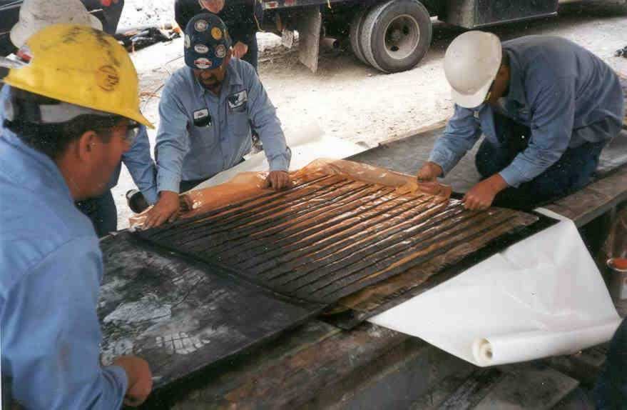
Another advantage is in the unique splice method specially designed for this belt construction that results in a strong, long lasting splice. Our splicing method is a long finger splice method where many cords are grouped into fingers instead of working with individual cords.
Picture:
http://www.afmindustries.com/product...spliceJPG.jpg
Also the ability to wrap smaller pullies is attractive to many system designers and those wishing to convert systems designed for fabric belting to steel. In this example minimum pulley diameters would be: Head 630mm, Tail 500mm, Snub 400mm
For increased troughing angles, Sempertrans manufacture another unique steel cable belt called Autostable. This belt is installed in many applications troughing over 45-degrees including 65-degrees and 135-degrees (enclosed triangle). But that is a different story altogether.
There are many other benefits of the Sempertrans S.F.B.T. designs to consider. I would be happy to answer any questions you might have.
Best regards,
Andrew Butterworth
AFM Industries ■
Selection Of St- Belt Cord Configurations
Kayem:
No Simple Answer - You Need to Know a Fair Bit More About the Problem
Selection of cord configuration has many attributes that alter ones best fit.
Our BELTSTAT code (www.conveyor-dynamics.com) has an algorithm that does a pretty good job at picking the cord configuration, splice pattern, length effect, etc.
There are a number of rules one must understand to optimize the splice strength per cord selection. One significant rule is where do you want the splice to fail - in the rubber or in the cord. Sounds strange? Consider that the splice can be made long enough to reduce the shear stress in rubber to cause the cord to fail first. Normally, we want the rubber to fail first to tell the tail of damage. If the cord fails first, then you have likely failed all splices but are not aware of it. Cords fail catastrophic. Rubber fails with physical evidence before parting.
Test you knowledge:
1. Is a odd number of cords in the splice equal in strength to an even number for the same ST rating? Answer. No. Why? Study the pattern of load behavior between cords and rubber t will become obvious. Read my papers. references found on our website.
2. Do all ST ratings produce the same splice strength? No. Get reference to papers on our website or download from CKIT www.ckit.co.za
3) With same cord diameter, do all splice patterns produce the same dynamic efficiency? No. a) Mfgrs' rubber fatigues differ.
b) read my papers
More on same:
1. Cord constructions differ as does the strength per diameter
2. Impregnation of cord changes the strength - here be careful mfgrs of steel cords also fiffer in technique and results
3. Splice configuration for various ST values - no good agreement
4. We designed and installed ST-5100 n/mm 2 step splice. No one had made such a recommendation till this was tested to +60% dynamics efficiency. Standards tell you 4 steps. Diifferent cords and different pitch and different strength/cord and different step efficiency Two steps are better than 4.
5. Rubber dynamic strength alters splice pattern and cord selection
6. Mfgrs prefer to hold limited number of cord diameters and the selection differs between mfgrs.
7. Din standards differ betweenunder ground and above ground for the same strength
8. The mfg wants to produce least cost belt. This means for the same ST to use least $$ ingredients. This will cause problems in splice construction and splice dynamic efficiency as per your comment on number of cords. Although your selection of cord diameters and numbers do not give the same strength.
There is much more than I have acknowledged, to provide a comprehensive and dilegent answer, in a proper way, than is appropriate for this forum. As you see, I also tend to be too lengthy in my responses. If you wish more, beyond reading our publications on splice dynamics and proper splice designs that control the proper cord selection, send me your query.
Lawrence Nordell
Conveyor Dynamics, Inc.
email: nordell@conveyor-dynamics.com ■
Second Comment
Kayem:
I have investigated your ST-1000 cord diameter and number. As you have suggested there are many possible choices. In this case, The first choice is not appropriate due to the allowable rubber gap between the cables in the splice. Following is a table of candidates, including mine, all with ST-1000 N/mm assuming 900 mm belt:
Diameter-------Number-------ST-XXXX--------Rubber Gap
--3.10-----------104-------------1040------------0.94
--3.60------------80(83)--------1076------------1.66
--4.00------------64(66)--------1030------------2.58
--3.80------------72-------------1050------------2.05 (my recommend.)
The gap between cords must be sufficient to be handled in the field. The number is around 2 mm. Your second selection could be a possible choice. I usually like to be close to 2 mm. If the noodle gum (gap dimension) is to fine, it is hard to control tolerances and the splice shape, hence the use of tackifiers. Tackifiers are bad. The solution is a combination of rubber and solvent. It reduces the strength of the splice.
Further, your second choice has 83 cables. Odd numbers are less efficient than even numbers as previously noted. Your last choice is more costly to the manufacturer in that is uses more rubber.
Another factor is the rock size and impact resistance required. High impact may require larger cord size to accomodate the higher wire to wire contact stress. Here too one can look at cord construction 7x7, 3x9x15, ... More wires equal more costs, for the same diameter. Line contact within the wire groups is better for fatigue and will yield a higher fatigue strength. This discussion can go on and on.
In conclusion, there is an algorithm that leads to the best choice. This algorithm differs between mfgrs. and their favorite suppliers of cords and cord cost and cord performance and availablility and .... understanding of all aspects of belt and splice technology.
Viva la tinto (VLT)
Lawrence Nordell
Conveyor Dynamics, Inc. ■
Re: Cord Configurations In Steel Cord Belts
Dear Mr. Nordell,
Thank you for your responses.
In installations that call for increased troughing angle OR installations where the impact load is very high, other factors remaining same, would the preferred Sg value range still remain around 2.0 mm ?
If not, what range of Sg values should one aim at ? ■
Steel Cord Belt Splice Design
Kayem:
New dimensions to the design are now imposed :
1. Increased troughing angle
2. High impact loads
These two additions to the belts design, at ST-1000 N/mm strength, require a further knowledge of the conveyors design to determine suitability including:
1. Belt cover thickness
2. Idler spacing
3. How big is the high impact - rock size, drop and chute design
4. Idler roll diameter
5. Idler roll troughing angle
6. Belt center-to-center length
7. Convex curve design
8. Trough transition at the high tension zone
9. Belt width
In general, the belt cover thickness adds support in the thinner carcass range (15-20mm) and inhibits good troughing in the large carcass range (+30mm). The cord pitch, in this narrow construction range is less influential than the cover gauges when designing for troughability.
High impact may require increased cord size to protect against wire-to-wire fretting failure within the cord. Rock size and impact energy may require other trade-offs such as cover gauge, reinforcements, loading control, .....
The larger idler trough angle may not be suitable due to the pinching action at the wing to center roll junction. Here the trough spacing, roll diameter, cover gauges, convex curve radius, and the trough transition configuration have to be taken as part of a system design.
You are now introducing many more factors that cannot be taken independently. I think you need to put the design on the table and have it review in its entirety.
Lawrence Nordell
Conveyor Dynamics, Inc. ■

Cord Configurations in Steel Cord Belts
Given the belt width and the desired ST rating, it is possible to arrive at various cord number- cord pitch combinations for each standard cord diameter, assuming a certain edge rubber thickness.
For example, a ST 1000 rating can be achieved with -
104 x 3.1 Ö OR 83 x 3.6 Ö OR 66 x 4.0 Ö etc., going by the individual cord strengths of each type and a considering a 10% drop in cummulative strength.
I would like to know if their is any norm for the maximum pitch : cord diameter ratio or any such restriction to guide the optimal selection of cord pitch & number for any given cord diameter. I am, for the purpose of this query, ignoring the selection tables that form a part of the various standards.
I would also like to know the rationale behind any such thumb-rule / specification / restriction - preferably from the application angle. ■