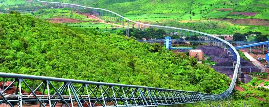
Belt Turn Over on Return side

40 m belt turnovers were installed on the system with five supporting zones. All different belt tensions, twisting and bending stresses and sag were looked at during the design of the turnover.
The turnovers served three distinct purposes:
- To keep the return side idlers clean. This increases the idler life and reduces maintenance and belt vibration.
- To prevent excessive fatiguing of the belt at the idler junction joint due the three roll return idlers.
- To Reduce the belt tensions. The belting incorporated a low rolling resistance rubber compound on the bottom belt cover, which would be in contact with both the carry and return side idlers.
Belt
The conveyor has a 1050 mm × ST 3150 N/mm belt. The cover thicknesses are 9.0 × 5.0 mm (top × bottom). The belt weight and the belt elasticity used in the analyses are 30.4 / 39.1 kg/m and 227,200 kN/m respectively. See Table 1 below for maximum belt tensions and safety factors.
| Maximum tension steady-state operation [kN] | Maximum tension start up operation [kN] | Maximum tension shut down operation [kN] | Safety factor non-steady-state operation [-] | |
|---|---|---|---|---|
| Empty | 304 | 365 | 477 | 6.93 |
| F load | 403 | 452 | 626 | 5.28 |
| I load | 304 | 388 | 465 | 7.11 |
| D load | 512 | 556 | 661 | 5.00 |
The belt is also equipped with rip detection system with sensors embedded in the top cover of the belt at 100 meter intervals.
Take Up Tension and Dynamics

The take up was an important part of the design with regards to the location and arrangement. The take-up was sized by considering all load cases with regards to belt sag, belt drift and the operational conditions. Dynamic analysis was also carried out to predict the displacement of the take up and counterweight at all possible conditions. Fig. 11 shows the tension distribution.
The total take up travel with double reeve system concluded to a travel of 20 m. The take-up travel due to tension variation during operation, the so-called tension travel, is summarized in Table 2 and Fig. 12 shows the take up travel during start up.
| Dynamic tension travel (max-min) | 7.30 m |
|---|---|
| Thermal growth | 2.00 m |
| Belt age creep | 2.90 m |
| 2 splices | 3.20 m |
| Clearance | 4.60 m |
| Total travel | 20.0 m |

Pulley Design

The pulleys in the conveyor system are arranged as shown in Fig. 3 (turnovers at the head and tail pulley are not shown). The pulley design considers major tensions only for the selection of shaft, bearing, end disk and shell design. All pulleys were analyzed using Finite Element Analysis software as shown in Fig. 13.
A 1400 mm diameter tail pulley was selected with 410 mm hub diameter shaft which stepped down to 340 mm diameter on the bearings. The head pulley is equipped with a 1250 mm shell diameter with 380 mm on the hub and 340 mm diameter on the bearings.


