5. Final Design
The client trialled 2 frames to reduce risk and evaluate the system’s ability to survive in the harsh application. A few areas for improvement to the design were made to make the complete system client friendly for install and maintenance, and improve the overall reliability such as:
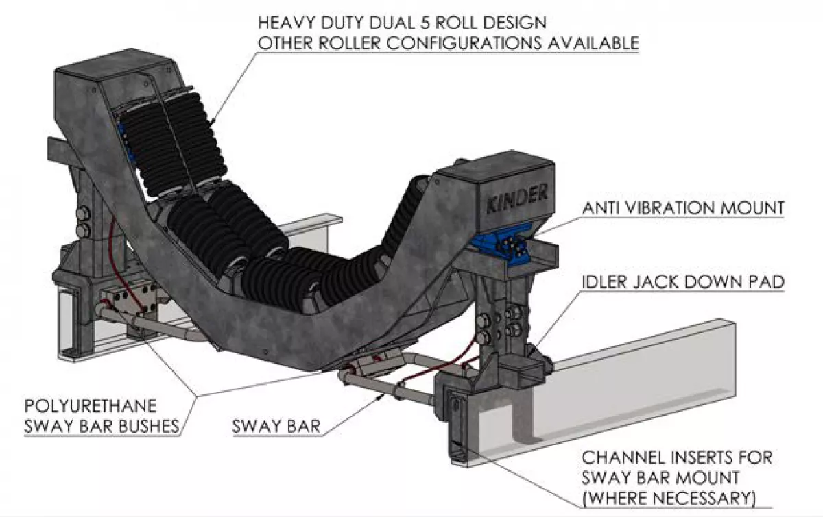
- 10 mm roller mount plate to counter the slot elongation seen on the current design (larger than current 8 mm). Further reducing this issue was the use of thicker retaining plates to fix the roller from springing back after impact.
- Channel inserts added to mount the sway bar blocks to the fixed part of the assembly. This allowed the sway bar to bend to the centre, allowing for a more compact system. It was also designed to stop rotation of the foot mount which was snapping the heads off the mount bolt.
- Jack down pad was extended to utilise a greater hydraulic jack range. This didn’t require the use of a specific type.
- Placing the rollers higher with respect to the transom plates. This allows the roller lift to be minimised when replacing them.
- Holes added for lifting of the main frame into place.
The trial units performed well and are still installed 12 months later. The feedback from site was that the frames were more reliable, and rollers needed to be changed out much less frequently. Whilst no data was obtained in terms of belt life improvement, the client ordered 6 more to fit out another transfer area where the belt will be replaced only when these are installed. The client is also expected to fit out the remainder of the transfer area where the trial units were fitted also.

A 3-month inspection was carried out at the shutdown following the trial install. The anti-vibration mounts were found to settle, whereby they remain depressed, even when the conveyor was not running (mass of rollers, frame and belt only). To counter this, a shim insertion system was incorporated to the new design and retrofitted to the trial units for the belt profile to remain the same, thus limiting spillage. This system utilised the jack down bolts to pressure the transom frame against the anti-vibration mount, creating a gap for a finger shim to then be inserted.

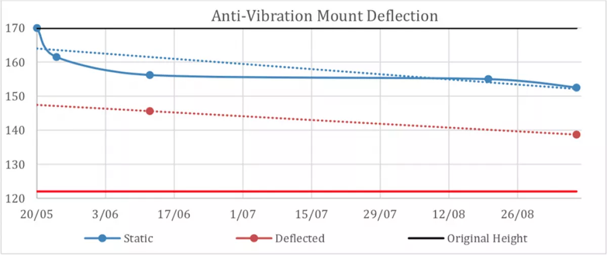
Advice was also sought from Rosta Australia regarding spring set, who stated it was likely due to ‘cold flow’; a settling of the anti-vibration mount which is a normal occurrence. This was found to have stabilised shortly after installation (Fig. 33). A ‘condemned’ anti-vibration mount height was also sought, for the customer to know exactly when the unit needed to be changed out.
The level given was the most allowable compression for the given unit of 138 mm. Given the anti-vibration mount was achieving a maximum of 14 mm of compression, and with a bottom out height of 122 mm, there would still be clearance under compression even at this condemned height.