

Re: Rolling Linear Grizzly
Tim
I am not sure if the "reciprocating grizzly feeder" will give you what you want - namely screening. ■
Will Not Screen
I do agree with ziggy, that type of device is meant basically to move material from point A to B down its length.......not meant to screen.
Used a lot in foundries to move small casted parts, used for moving woodwaste also from a grinder for example.
Not really setup to screen .......as it does not LIFT the material to allow coarse to separate from fines.......a screening theory.
George Baker ■
Better Idea Maybe......
Take wirecloth off your little vibrating screener......and install self relieving steel scalper bar arrangement, preferably by bolting onto the sideplates by means of a bent edge arrangement....vs welding on vib screen box. NOT GOOD.
Or..put flat 1/4" thick plate with say.......1 /2 or 2 inch round or square holes in line........and then weld a skid bar say 1"x2" down plate between holes to skid off big stuff and add wash bars above that........BOB's your uncle....
Try to lay the material onto the screen deck vs DROP from any height.....to avoid abuse to mechanism.
Should work.......PS...Try hard to keep overall weight down.....it will kill the stroke.....action...deaden...make weaker...etc.
George Baker MODERATOR ■
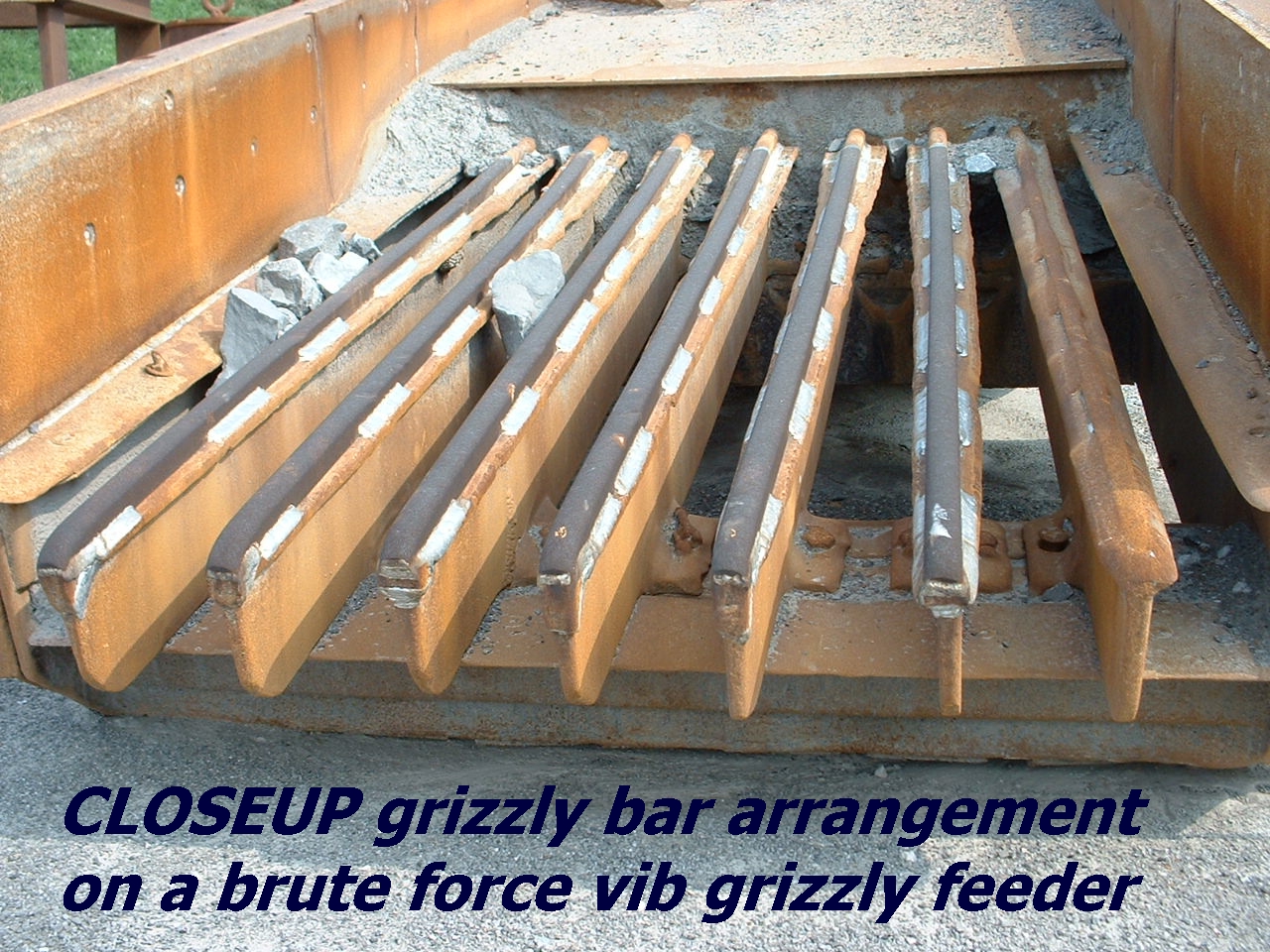
Pic Of Grizzly Bar For Vgf
Screen Deck Pics
Thanks for all the thoughts guys.
Had to make a trip out to the claim.
The distance between the shaft housing and lower screen is about 3 “. With a few modifications, there’s room for 6”.
Would this present any worthy benefits? If so and given the clearance, if I use the 1” minus as lower deck, what would you recommend for the upper deck?
With this 2 by 6, what might pass over without bogging the machine down or causing excess wear?
Attachments
■
Use Plate On Top Deck
Suggest a 3/8" THICK a/r steel plate with burned 3" diameter holes in it. I would weld 1/2thick by 1" high flat bars down length of plate between holes.
The flat bars will help SKID the oversize off the deck and keep it somewhat off sticking into the holes hopefully and act as a guard deck for the 1" below.
Square openings will do also if thats all you can get or do.
IS the purpose to size to 1" minus or no? I did not think that was the purpose.
If it is not the purpose.....do all the separation on the top deck only setup. ■
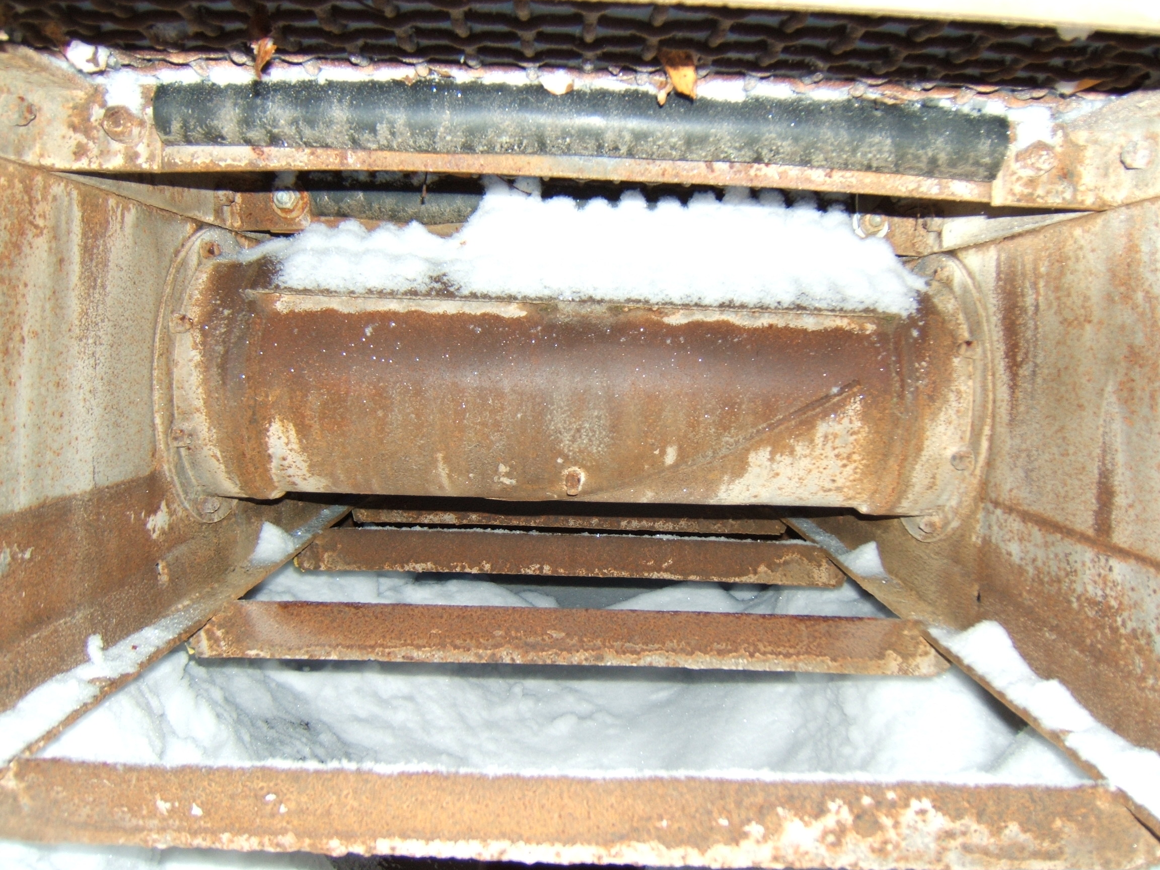
The Second Deck Position
Hmmmmmmm..........relooking closer at that SIMPLICITY.
That 2nd deck or deck support showing under MR SHAFT ASSEMBLY is NOT a screening deck position....just a brace deck setup.
There appears to be no holes in sideplate to stretch any wirecloth and there are no longitudinal rails to stretch any wirecloth over........so just a brace deck position.
TOP deck is setup for screening only it appears....welding in wirecloth will be a disaster....not recommended....but, YOU have a nice machine to work with there......OIL LUBE...yes? ■
1" Minus Two-Deck
With great appreciation - Excellent!
You're right, the pictures are obscure, but there are holes and bolt wedges along the lower level. So the 3" holes recomended is what I'll do. Should the hole patern be in a streight line, or should it be staggerred between the 1/2" runners to maximize surface coverage? Also, what hole and bar spacing do you think is best?
Would trimmed off grader blades cutting egdes, approx 5/8" thick, fit the bill?
The objective is 1" minus. Sorry for double checking, but I just want make sire that the 3 1/2" clearance under shaft housing will be sufficient?
Thanks also for the lubrication question. Bearrings are fitted with grease nipples.
Respectfully, ■
Hole Pattern
Staggered would be preferred....for more coverage generally. BUT
I would recommend straight line...so easier to attach riser or skid bars down deck length. Cutting edge or whatever you can manuever will work in a pinch or course.
We do wanna try to keep the weight down at all times if possible.
At the end of this, you may have to add a bit of flywheel weight to get a tad more stroke if it bogs it down too much....but, should be ok....cross that bridge later. DO NOT speed the machine up.
You wanna have minium 1/2" margin between holes for integrity...maybe even 3/4"
Good luck...George ■
Grizzly Bar Height, Spacing, Taper Ratio
Greetings, 1000$/oz!!!
following with plan of burning 3" holes in upper level 3/8" AR plate, and moving 1" screen down under in Simplicity 2' x 6', two bearing wet-screendeck. Feed size will be restricted to occasional 18" and minus with use of 10 ton hoe feeding a stationary hopper approx 1/2 yrd/min. Total water supply will be approx. 700 gal/min.
Now for the grizzly bars you illustrated. Is there a rule of thumb for determing taper of height and width of grizzly bars?
I remember seeing this somewhere in the forum a few years ago but cant retrace it.
With your advice on weight restriction, and since it's already on the burn table, could I also use the 3/8" AR plate, instead of 1/2" you recomended, for fabrication of these bars?
Again with the weight factor in mind, can I use 6" x 1/4" AR properly welded to grizzly plate as sides/bolting surface, and as additional protection of existing sides on washplant. More mounting bolts = less plate thickness?
Also, should adjustment holes be drilled in sides of little Simplicity for Grizzly plane-angle fine tunning. In this type of application, is Grizzly angle the same as lower level screen angle? I guess this depends alot on material size. But just trying to visuallise flow of material and a starting reference piont.
Thanks again and hope to post a pic of yellow soon. That is, once the all white stuff is gone. ■
Oops
Sorry George,
just re-read the whole thread and picked up your advise on the 1/4" side plates.
More notes required! ■
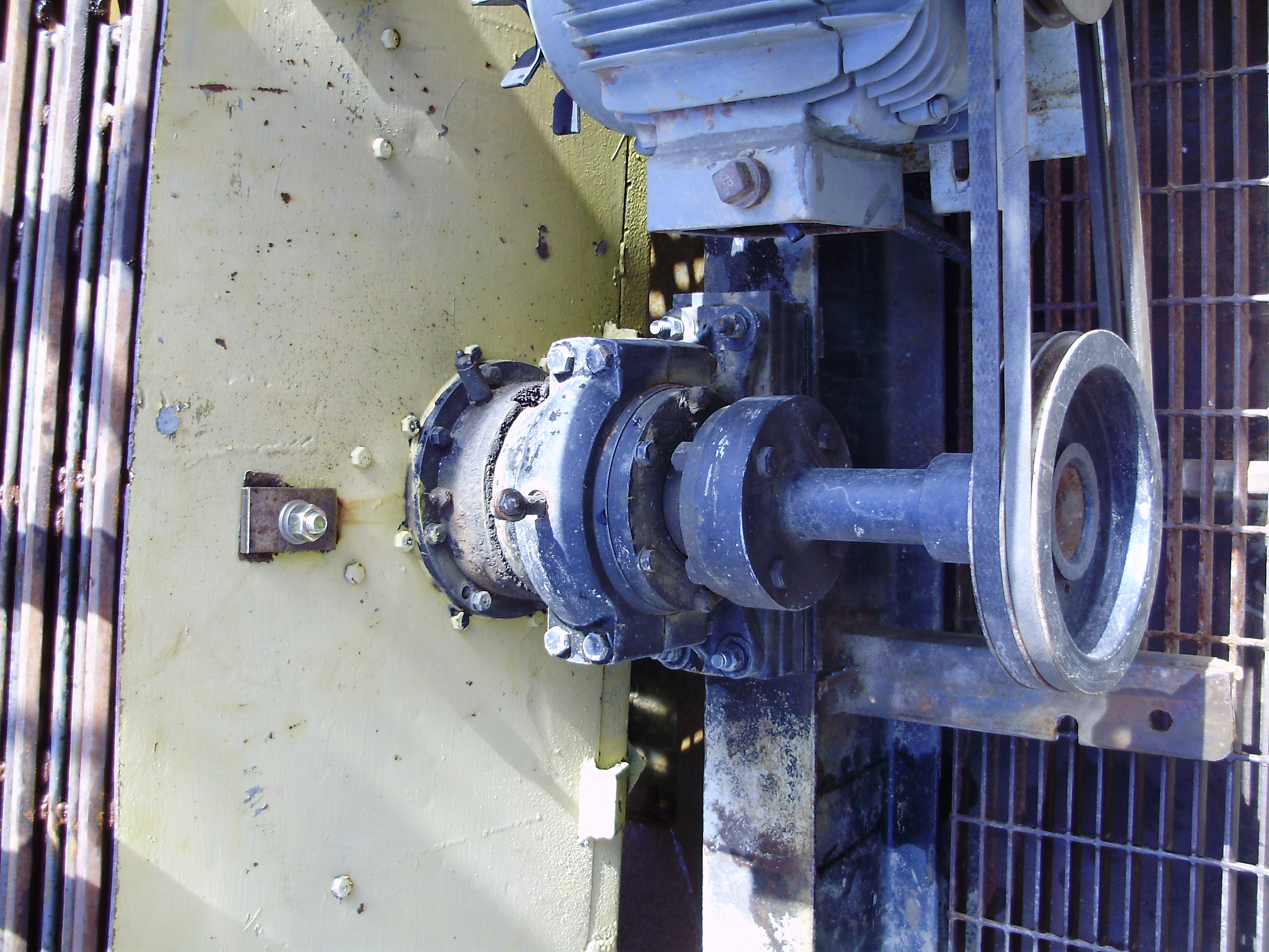
Heavier Screen = Lugging
Just modified a circle throw Simplicity 2’ x 6’ single deck screener. Swapped 1” wire cloth for perforated plate. Plate is 3\8” thick, with 5/8” x 4” long slotted openings. The plate also has 1” skid bars and 5\8” spacer bars attached. Estimated weight of new plate is 250 to 300 lbs.
Plate is intended to scalp off ” up to occasional 16” rounded slab rock. 600-700 gal/min water between hopper and deck.
Vibration is much more than with wire cloth, even without any material. In other discussions, tracing with a marker was mentioned, but this art form isn’t clear to me yet.
Upon recently reading one of a few of uncle George’s tips, I realise there should be rubber underlying the plate. Holes already drilled and plate was sucked down pretty tight. Probably half a day to re & re. Would strips of conveyor belting do, and does this situation require rubber underlay?
Back to main topic, any tips on tracing and forward looking ideas on weight/rpm changes to smooth things out a little.
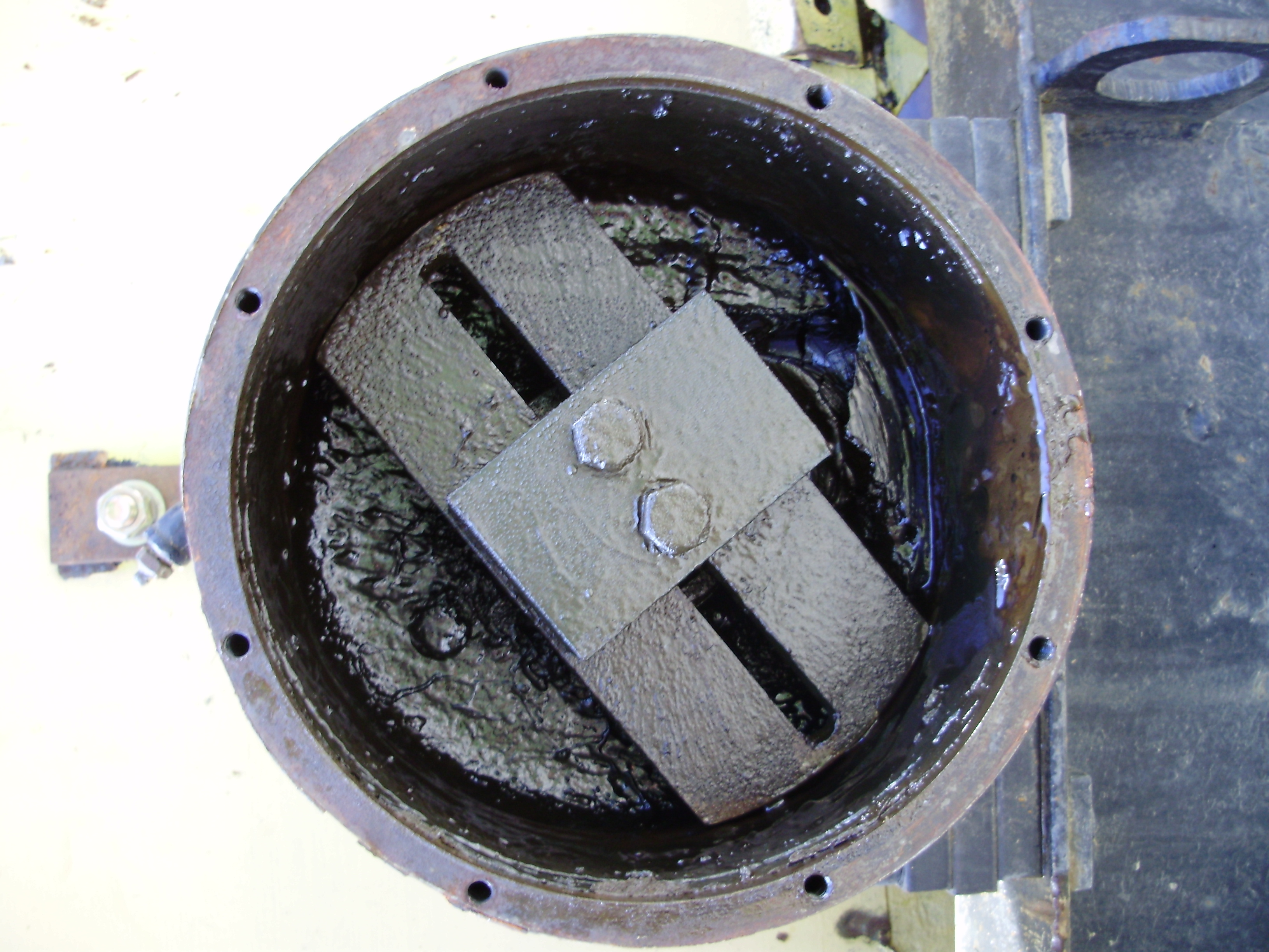
Attached are pictures of drive and tail ends of shaft. There doesn't appear to be any weights on drive end, although I exposed tail end. I'm assuming the center block with two bolts attaching it to shaft is the weight. How are adjustments made to this type of arrangement? Scribe exsisting spot, and move weight in or out, say 1mm at a time, until the right action is reached.
Thanks all,
Attachments
■

Rolling linear grizzly
Hello and thank you for sharing all your experience and
knowledge.
I have a rolling linear feeder that is driven by a connecting rod.
It has four 3" diam steel wheels and appears to have a stroke of
approx 6". The motion is strictly back and forth. There's no
motor, but the gear box appears to be for about 5hp.
The principle of it seems simple enough, and without critical
balancing, I could fabricate this type mechanism to drive a grizzly.
If practical, I would like to make a 4'W x 12'L grizzly supported
over my existing 2'W x 6'L Simplicity wet screen (1" openings).
The material is alluvial gravels ranging from 3 feet in diam to
silt/clay. Attached is picture of this. Horizon above black clay is
pay horizon. I would like to process the larger rocks to wash
gold off.
What would the grizzly openings, horsepower, and stroke cycle
and length be?
Thanks again
Attachments
horizons (JPG)
■